Front I/O module
The front I/O module provides controls, connectors and LEDs. The front I/O module varies by model.
Front I/O module (on rack latch) 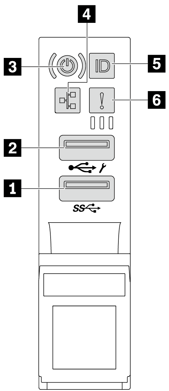 | Front I/O module (on media bay) 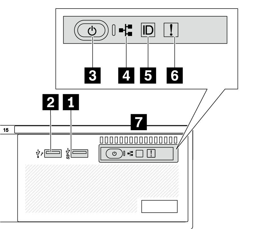 |
| Callout | Callout |
|---|---|
| 1 USB 3 (5 Gbps) connector | 2 USB 2.0 connector with XClarity Controller management |
| 3 Power button with power status LED | 4 Network activity LED (for OCP module) |
| 5 System ID button with system ID LED | 6 System error LED |
| 7 Front operator panel or Integrated Diagnostics Panel |
1 USB 3 (5 Gbps) connector
The USB 3.2 Gen 1 (5 Gbps) connector can be used to attach a USB-compatible device, such as a USB keyboard, USB mouse, or USB storage device.
2 USB 2.0 connector with XClarity Controller management
If the connector is set for USB 2.0 function, it can be used to attach a USB-compatible device, such as a USB keyboard, USB mouse, or USB storage device.
If the connector is set for XClarity Controller management function, it can be used to connect the server to an android or iOS device, where you can then install and launch the Lenovo XClarity Mobile app to manage the system using XClarity Controller.
For details about using the Lenovo XClarity Mobile app, refer to Lenovo XClarity Administrator Mobile app online documentation.
If the connector is set to have both functions, you can press the system ID button for three seconds to switch between the two functions.
3 Power button with power status LED
| Status | Color | Description |
|---|---|---|
| Off | None | Power is not present, or the power supply has failed. |
| Fast blinking (about four flashes per second) | Green | The server is off, but the XClarity Controller is initializing, and the server is not ready to be powered on. |
| Slow blinking (about one flash per second) | Green | The server is off and is ready to be powered on (standby state). |
| Solid on | Green | The server is on and running. |
4 Network activity LED
| NIC adapter | Network activity LED |
|---|---|
| OCP module | Support |
| PCIe NIC adapter | Not support |
| Status | Color | Description |
|---|---|---|
| On | Green | The server is connected to a network. |
| Blinking | Green | The network is connected and active. |
| Off | None | The server is disconnected from the network. Note If the network activity LED is off when an OCP module is installed, check the network ports in the rear of your server to determine which port is disconnected. |
5 System ID button with system ID LED
Use this system ID button and the blue system ID LED to visually locate the server. Each time you press the system ID button, the state of the system ID LED changes. The LED can be changed to on, blinking, or off. You can also use the Lenovo XClarity Controller or a remote management program to change the state of the system ID LED to assist in visually locating the server among other servers.
If the XClarity Controller USB connector is set to have both the USB 2.0 function and XClarity Controller management function, you can press the system ID button for three seconds to switch between the two functions.
6 System error LED
The system error LED provides basic diagnostic functions for your server. If the system error LED is lit, one or more LEDs elsewhere in the server might also be lit to direct you to the source of the error.
| Status | Color | Description | Action |
|---|---|---|---|
| On | Yellow | An error has been detected on the server. Causes might include but are not limited to the following errors:
|
|
| Off | None | The server is off, or the server is on and is working correctly. | None. |
7 Front operator panel or Integrated Diagnostics Panel
The front operator panel provides controls and LEDs, including the power button with power status LED, network activity LED, system ID button with system ID LED, and system error LED.
Depending on the server model, the server comes with the front operator panel with LCD display (called Integrated Diagnostics Panel) or the front operator panel without LCD display.
Figure 1. Integrated Diagnostics Panel (with LCD display) 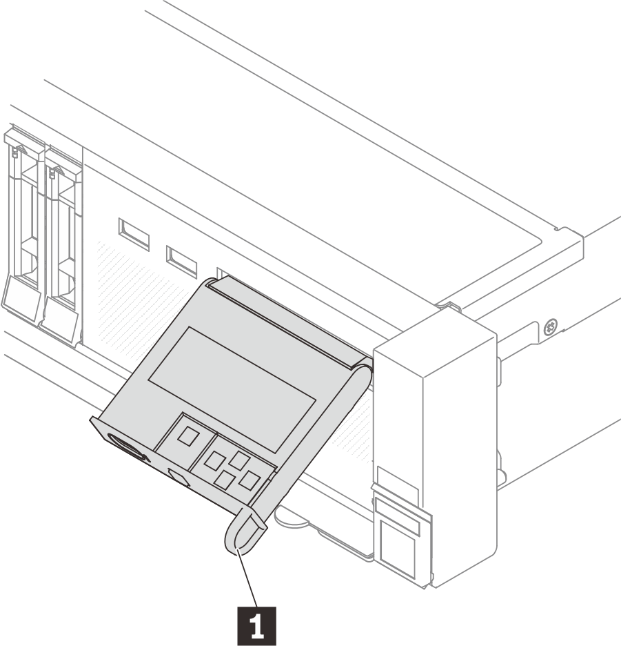 | Figure 2. Front operator panel (without LCD display) 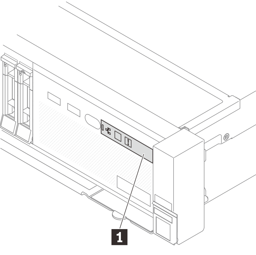 |