Servermodell mit 24 x 2,5-Zoll-Laufwerkpositionen an der Vorderseite (NVMe)
Dieser Abschnitt enthält Informationen zur Kabelführung für das Servermodell mit drei vorderen 8 x 2,5-Zoll-NVMe-Rückwandplatinen.
Konfiguration 1: drei vordere 8 x 2,5-Zoll-NVMe-Rückwandplatinen, zwei 810-4P oder 1610-4P NVMe-Switch-Karten
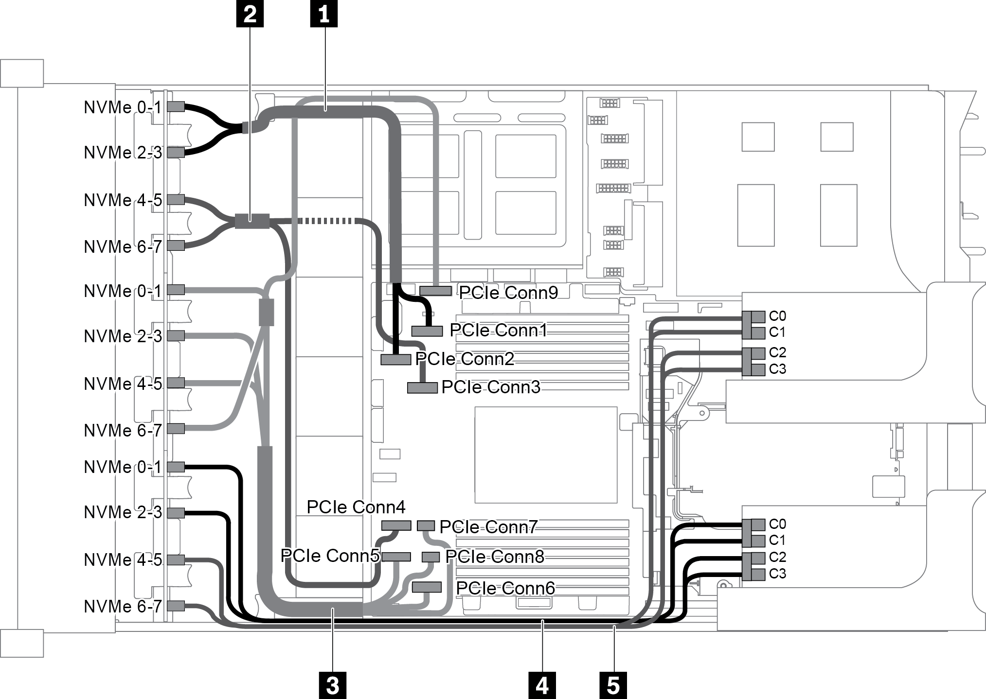
| Kabel | Von | Bis |
|---|---|---|
| 1 NVMe-Signalkabel | NVMe-Anschluss 0-1 auf der NVMe-Rückwandplatine 1 | PCIe-Anschluss 1 auf der Systemplatine |
| NVMe-Anschluss 2-3 auf der NVMe-Rückwandplatine 1 | PCIe-Anschluss 2 auf der Systemplatine | |
| 2 NVMe-Signalkabel | NVMe-Anschluss 4-5 auf der NVMe-Rückwandplatine 1 | PCIe-Anschluss 3 auf der Systemplatine |
| NVMe-Anschluss 6-7 auf der NVMe-Rückwandplatine 1 | PCIe-Anschluss 4 auf der Systemplatine | |
| 3 NVMe-Signalkabel | NVMe-Anschluss 0-1 auf der NVMe-Rückwandplatine 2 | PCIe-Anschluss 5 auf der Systemplatine |
| NVMe-Anschluss 2-3 auf der NVMe-Rückwandplatine 2 | PCIe-Anschluss 6 auf der Systemplatine | |
| NVMe-Anschluss 4-5 auf der NVMe-Rückwandplatine 2 | PCIe-Anschlüsse 7 und 8 auf der Systemplatine | |
| NVMe-Anschluss 6-7 auf der NVMe-Rückwandplatine 2 | PCIe-Anschluss 9 auf der Systemplatine | |
| 4 NVMe-Signalkabel | NVMe-Anschluss 0-1 auf der NVMe-Rückwandplatine 3 | Anschlüsse C0 und C1 auf der Switch-Karte 1 |
| NVMe-Anschluss 2-3 auf der NVMe-Rückwandplatine 3 | Anschlüsse C2 und C3 auf der Switch-Karte 1 | |
| 5 NVMe-Signalkabel | NVMe-Anschluss 4-5 auf der NVMe-Rückwandplatine 3 | Anschlüsse C0 und C1 auf der Switch-Karte 2 |
| NVMe-Anschluss 6-7 auf der NVMe-Rückwandplatine 3 | Anschlüsse C2 und C3 auf der Switch-Karte 2 |
Konfiguration 2: drei vordere 8 x 2,5-Zoll-NVMe Rückwandplatinen, eine 1611-8P-NVMe-Switch-Karte
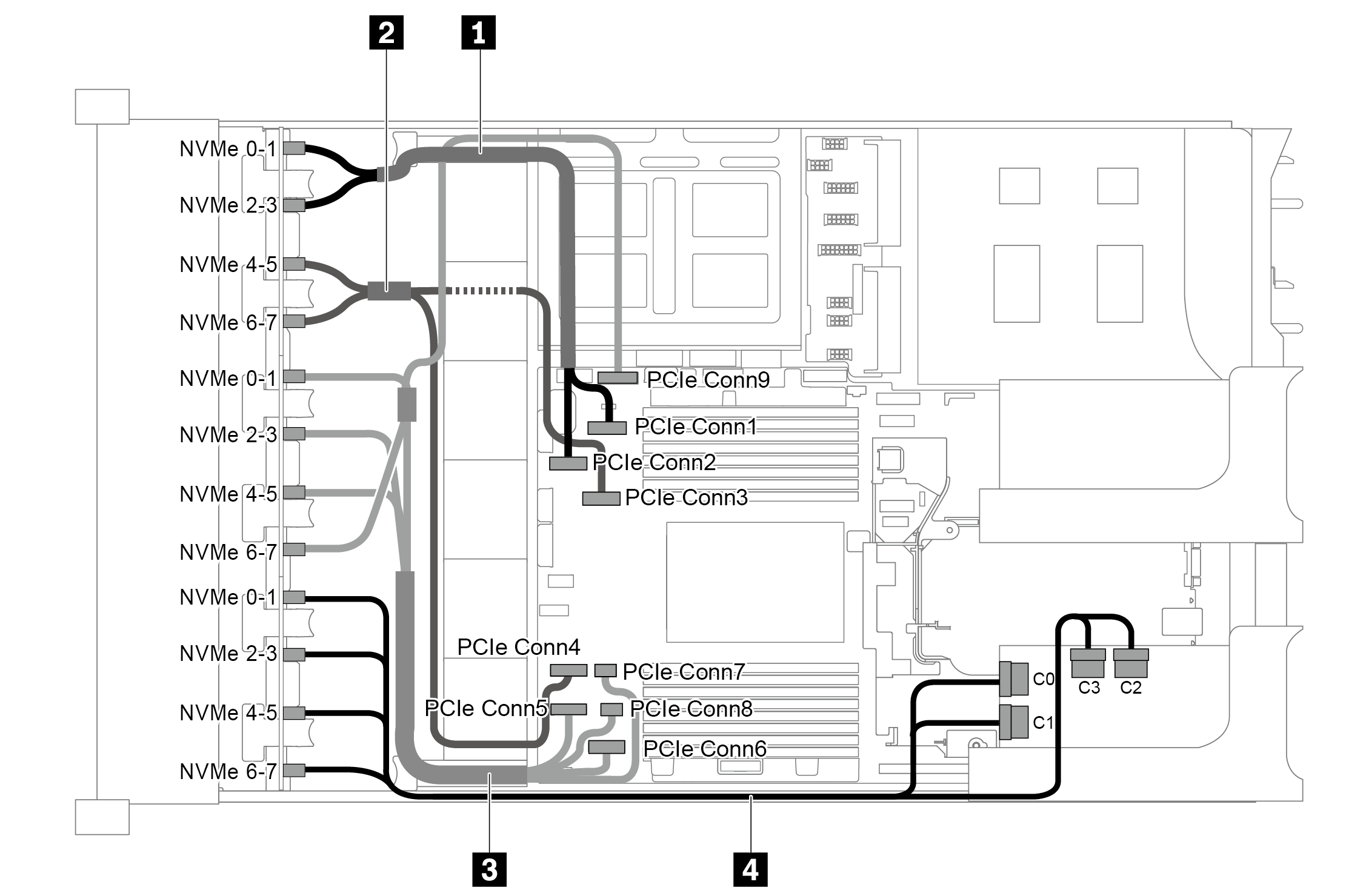
| Kabel | Von | Bis |
|---|---|---|
| 1 NVMe-Signalkabel | NVMe-Anschluss 0-1 auf der NVMe-Rückwandplatine 1 | PCIe-Anschluss 1 auf der Systemplatine |
| NVMe-Anschluss 2-3 auf der NVMe-Rückwandplatine 1 | PCIe-Anschluss 2 auf der Systemplatine | |
| 2 NVMe-Signalkabel | NVMe-Anschluss 4-5 auf der NVMe-Rückwandplatine 1 | PCIe-Anschluss 3 auf der Systemplatine |
| NVMe-Anschluss 6-7 auf der NVMe-Rückwandplatine 1 | PCIe-Anschluss 4 auf der Systemplatine | |
| 3 NVMe-Signalkabel | NVMe-Anschluss 0-1 auf der NVMe-Rückwandplatine 2 | PCIe-Anschluss 5 auf der Systemplatine |
| NVMe-Anschluss 2-3 auf der NVMe-Rückwandplatine 2 | PCIe-Anschluss 6 auf der Systemplatine | |
| NVMe-Anschluss 4-5 auf der NVMe-Rückwandplatine 2 | PCIe-Anschlüsse 7 und 8 auf der Systemplatine | |
| NVMe-Anschluss 6-7 auf der NVMe-Rückwandplatine 2 | PCIe-Anschluss 9 auf der Systemplatine | |
| 4 NVMe-Signalkabel | NVMe-Anschlüsse 0-1 und 2-3 an der NVMe-Rückwandplatine 3 | Anschlüsse C0 und C1 auf der Switch-Karte 1 |
| NVMe-Anschlüsse 4-5 und 6-7 an der NVMe-Rückwandplatine 3 | Anschlüsse C2 und C3 auf der Switch-Karte 1 |
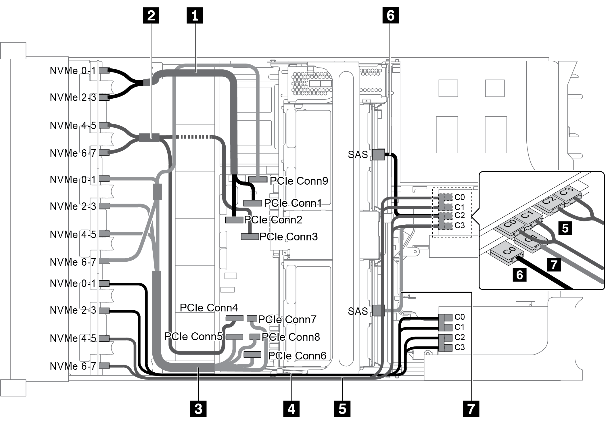
Konfiguration 3: drei vordere 8 x 2,5-Zoll-NVMe-Rückwandplatinen, eine hintere Laufwerkhalterung (SAS/SATA), zwei 810-4P- oder 1610-4P-NVMe-Switch-Karten, ein 8i RAID/HBA-Adapter
Diese Konfiguration unterstützt eine hintere Laufwerkhalterung mit einer 4 x 2,5-Zoll-SAS/SATA-Rückwandplatine für Laufwerke.
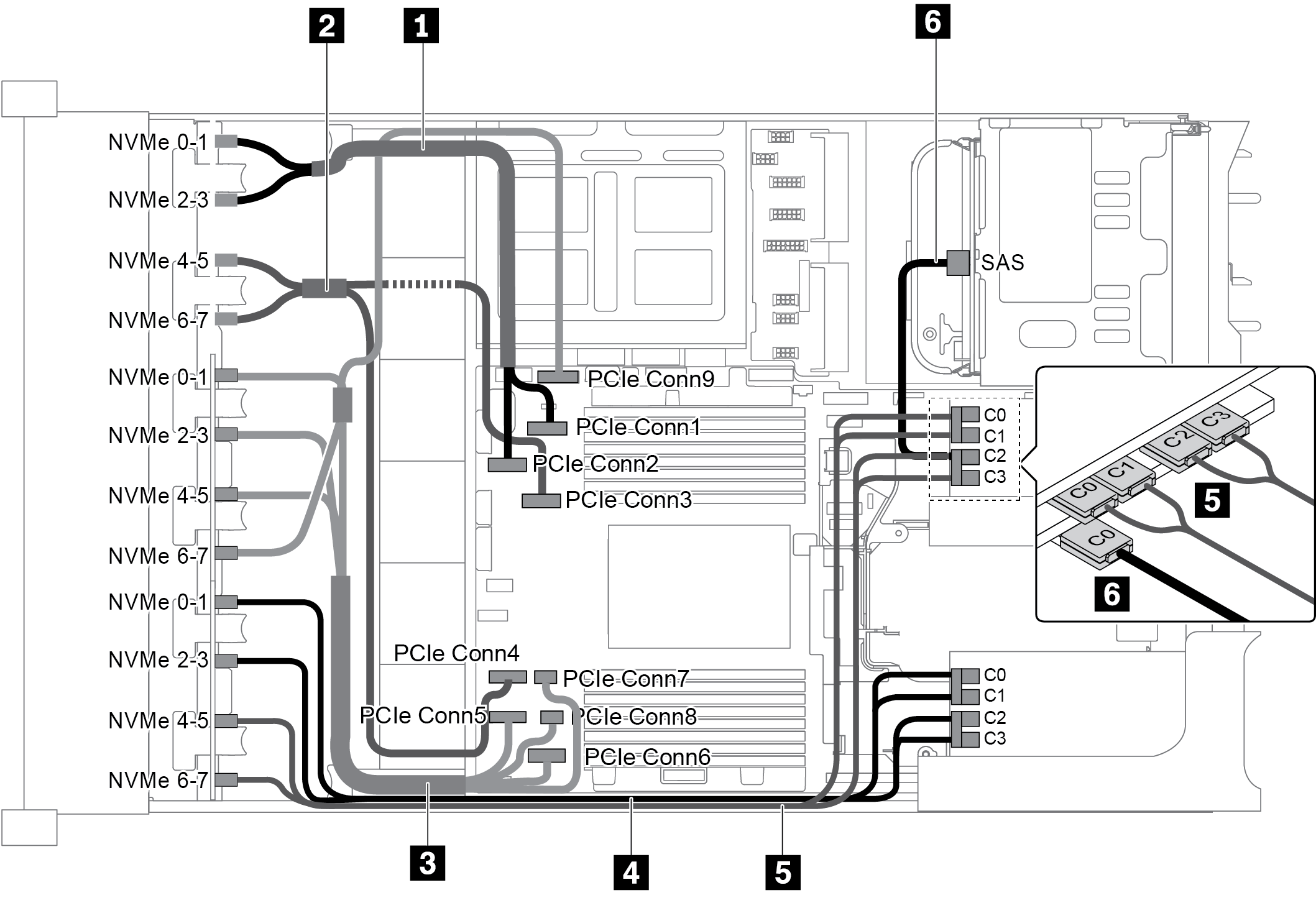
| Kabel | Von | Bis |
|---|---|---|
| 1 NVMe-Signalkabel | NVMe-Anschluss 0-1 auf der NVMe-Rückwandplatine 1 | PCIe-Anschluss 1 auf der Systemplatine |
| NVMe-Anschluss 2-3 auf der NVMe-Rückwandplatine 1 | PCIe-Anschluss 2 auf der Systemplatine | |
| 2 NVMe-Signalkabel | NVMe-Anschluss 4-5 auf der NVMe-Rückwandplatine 1 | PCIe-Anschluss 3 auf der Systemplatine |
| NVMe-Anschluss 6-7 auf der NVMe-Rückwandplatine 1 | PCIe-Anschluss 4 auf der Systemplatine | |
| 3 NVMe-Signalkabel | NVMe-Anschluss 0-1 auf der NVMe-Rückwandplatine 2 | PCIe-Anschluss 5 auf der Systemplatine |
| NVMe-Anschluss 2-3 auf der NVMe-Rückwandplatine 2 | PCIe-Anschluss 6 auf der Systemplatine | |
| NVMe-Anschluss 4-5 auf der NVMe-Rückwandplatine 2 | PCIe-Anschlüsse 7 und 8 auf der Systemplatine | |
| NVMe-Anschluss 6-7 auf der NVMe-Rückwandplatine 2 | PCIe-Anschluss 9 auf der Systemplatine | |
| 4 NVMe-Signalkabel | NVMe-Anschluss 0-1 auf der NVMe-Rückwandplatine 3 | Anschlüsse C0 und C1 auf der Switch-Karte 1 |
| NVMe-Anschluss 2-3 auf der NVMe-Rückwandplatine 3 | Anschlüsse C2 und C3 auf der Switch-Karte 1 | |
| 5 NVMe-Signalkabel | NVMe-Anschluss 4-5 auf der NVMe-Rückwandplatine 3 | Anschlüsse C0 und C1 auf der Switch-Karte 2 |
| NVMe-Anschluss 6-7 auf der NVMe-Rückwandplatine 3 | Anschlüsse C2 und C3 auf der Switch-Karte 2 | |
| 6 SAS-Signalkabel | SAS-Anschluss an der hinteren Laufwerkhalterung | C0-Anschluss auf dem 8i RAID/HBA-Adapter |
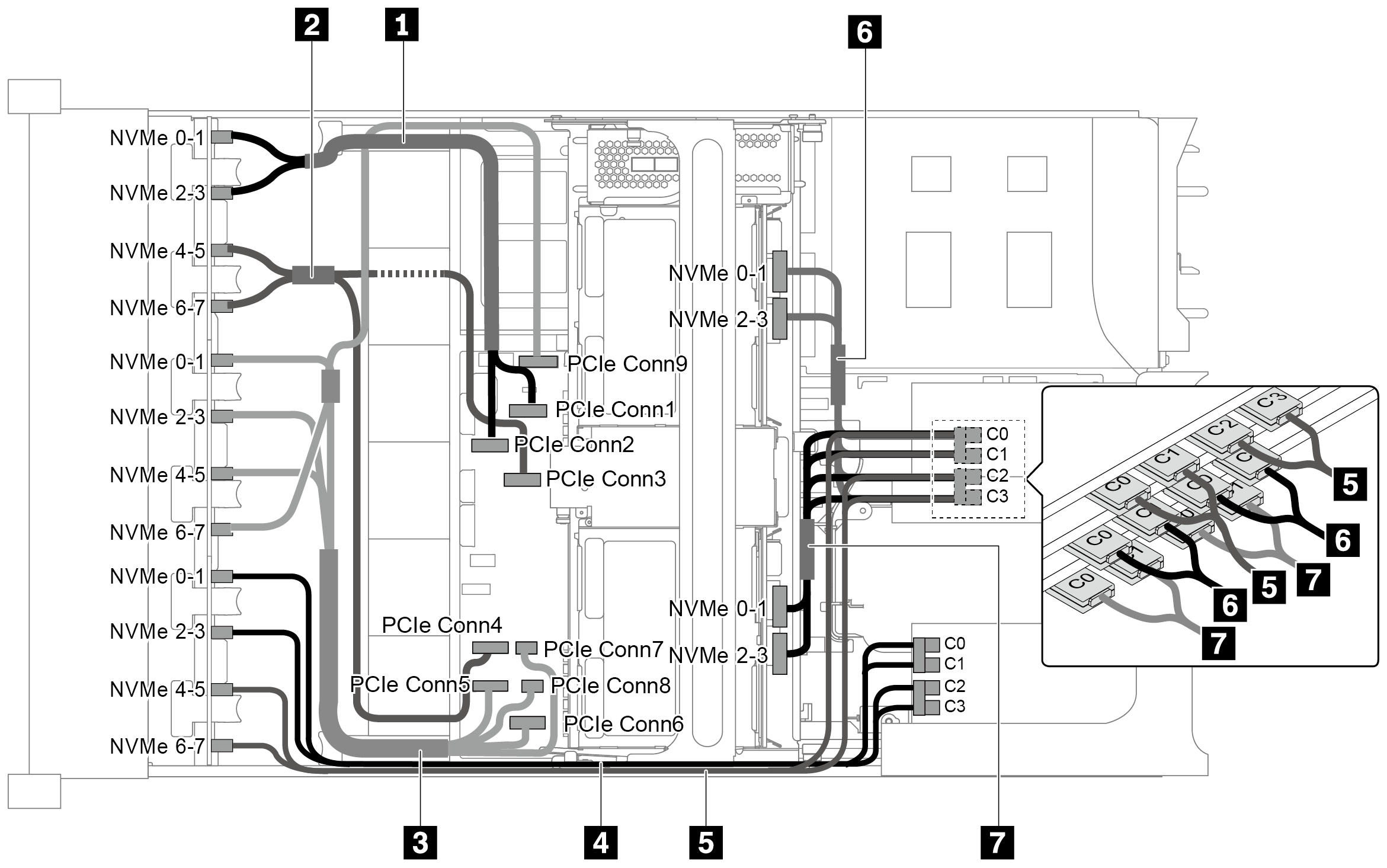
Konfiguration 4: drei vordere 8 x 2,5-Zoll-NVMe-Rückwandplatinen, eine hintere Laufwerkhalterung (NVMe), drei 810-4P- oder 1610-4P-NVMe-Switch-Karten
Diese Konfiguration unterstützt eine hintere Laufwerkhalterung mit einer 4 x 2,5-Zoll-NVMe-Rückwandplatine für Laufwerke.
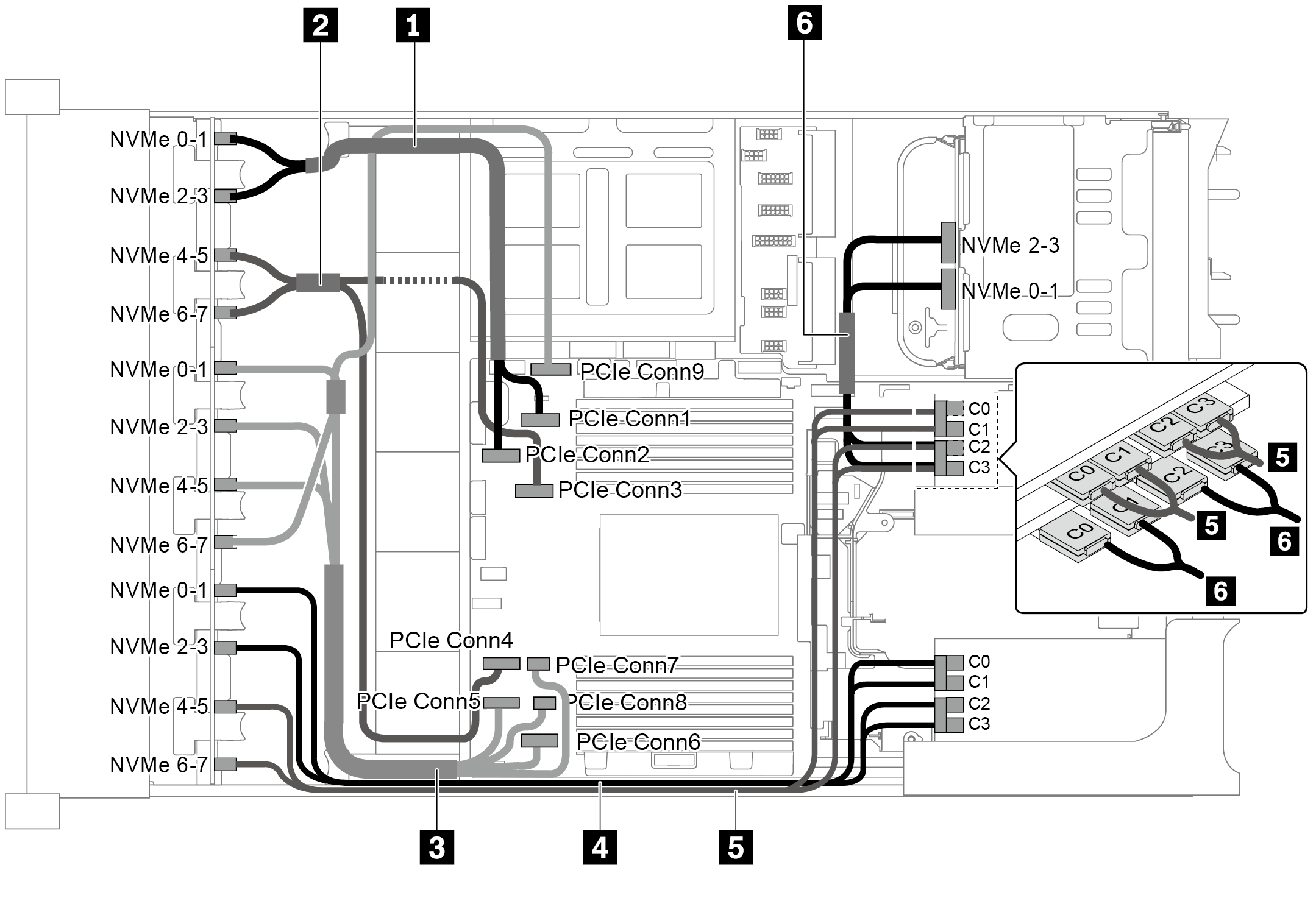
| Kabel | Von | Bis |
|---|---|---|
| 1 NVMe-Signalkabel | NVMe-Anschluss 0-1 auf der NVMe-Rückwandplatine 1 | PCIe-Anschluss 1 auf der Systemplatine |
| NVMe-Anschluss 2-3 auf der NVMe-Rückwandplatine 1 | PCIe-Anschluss 2 auf der Systemplatine | |
| 2 NVMe-Signalkabel | NVMe-Anschluss 4-5 auf der NVMe-Rückwandplatine 1 | PCIe-Anschluss 3 auf der Systemplatine |
| NVMe-Anschluss 6-7 auf der NVMe-Rückwandplatine 1 | PCIe-Anschluss 4 auf der Systemplatine | |
| 3 NVMe-Signalkabel | NVMe-Anschluss 0-1 auf der NVMe-Rückwandplatine 2 | PCIe-Anschluss 5 auf der Systemplatine |
| NVMe-Anschluss 2-3 auf der NVMe-Rückwandplatine 2 | PCIe-Anschluss 6 auf der Systemplatine | |
| NVMe-Anschluss 4-5 auf der NVMe-Rückwandplatine 2 | PCIe-Anschlüsse 7 und 8 auf der Systemplatine | |
| NVMe-Anschluss 6-7 auf der NVMe-Rückwandplatine 2 | PCIe-Anschluss 9 auf der Systemplatine | |
| 4 NVMe-Signalkabel | NVMe-Anschluss 0-1 auf der NVMe-Rückwandplatine 3 | Anschlüsse C0 und C1 auf der Switch-Karte 1 |
| NVMe-Anschluss 2-3 auf der NVMe-Rückwandplatine 3 | Anschlüsse C2 und C3 auf der Switch-Karte 1 | |
| 5 NVMe-Signalkabel | NVMe-Anschluss 4-5 auf der NVMe-Rückwandplatine 3 | Anschlüsse C0 und C1 auf der Switch-Karte 2 |
| NVMe-Anschluss 6-7 auf der NVMe-Rückwandplatine 3 | Anschlüsse C2 und C3 auf der Switch-Karte 2 | |
| 6 NVMe-Signalkabel | NVMe-Anschluss 0-1 auf der hinteren NVMe-Rückwandplatine | Anschlüsse C0 und C1 auf der Switch-Karte 3 |
| NVMe-Anschluss 2-3 auf der hinteren NVMe-Rückwandplatine | Anschlüsse C2 und C3 auf der Switch-Karte 3 |
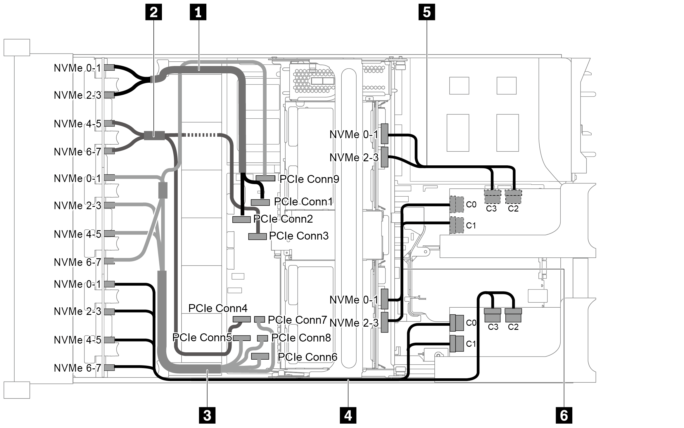
Konfiguration 5: drei vordere 8 x 2,5-Zoll-NVMe-Rückwandplatinen, eine mittlere Laufwerkhalterung (SAS/SATA), zwei 810-4P- oder 1610-4P-NVMe-Switch-Karten, ein 8i RAID/HBA-Adapter
Diese Konfiguration unterstützt eine mittlere 2,5-Zoll-Laufwerkhalterung mit zwei 4 x 2,5-Zoll-SAS/SATA-Rückwandplatinen für Laufwerke.
Stellen Sie bei Installation eines RAID/HBA-Adapters (Gen. 4) sicher, dass Sie das entsprechende Gen‑4-Kabel verwenden:
ThinkSystem SR655 2.5" & 3.5" SAS/SATA 4/8-Bay Middle Backplane X40 RAID Cable Kit
| Kabel | Von | Bis |
|---|---|---|
| 1 NVMe-Signalkabel | NVMe-Anschluss 0-1 auf der NVMe-Rückwandplatine 1 | PCIe-Anschluss 1 auf der Systemplatine |
| NVMe-Anschluss 2-3 auf der NVMe-Rückwandplatine 1 | PCIe-Anschluss 2 auf der Systemplatine | |
| 2 NVMe-Signalkabel | NVMe-Anschluss 4-5 auf der NVMe-Rückwandplatine 1 | PCIe-Anschluss 3 auf der Systemplatine |
| NVMe-Anschluss 6-7 auf der NVMe-Rückwandplatine 1 | PCIe-Anschluss 4 auf der Systemplatine | |
| 3 NVMe-Signalkabel | NVMe-Anschluss 0-1 auf der NVMe-Rückwandplatine 2 | PCIe-Anschluss 5 auf der Systemplatine |
| NVMe-Anschluss 2-3 auf der NVMe-Rückwandplatine 2 | PCIe-Anschluss 6 auf der Systemplatine | |
| NVMe-Anschluss 4-5 auf der NVMe-Rückwandplatine 2 | PCIe-Anschlüsse 7 und 8 auf der Systemplatine | |
| NVMe-Anschluss 6-7 auf der NVMe-Rückwandplatine 2 | PCIe-Anschluss 9 auf der Systemplatine | |
| 4 NVMe-Signalkabel | NVMe-Anschluss 0-1 auf der NVMe-Rückwandplatine 3 | Anschlüsse C0 und C1 auf der Switch-Karte 1 |
| NVMe-Anschluss 2-3 auf der NVMe-Rückwandplatine 3 | Anschlüsse C2 und C3 auf der Switch-Karte 1 | |
| 5 NVMe-Signalkabel | NVMe-Anschluss 4-5 auf der NVMe-Rückwandplatine 3 | Anschlüsse C0 und C1 auf der Switch-Karte 2 |
| NVMe-Anschluss 6-7 auf der NVMe-Rückwandplatine 3 | Anschlüsse C2 und C3 auf der Switch-Karte 2 | |
| 6 SAS-Signalkabel | SAS-Anschluss auf der mittleren Rückwandplatine 1 | 8i RAID/HBA-Adapter
|
| 7 SAS-Signalkabel | SAS-Anschluss auf der mittleren Rückwandplatine 2 | 8i RAID/HBA-Adapter
|
Konfiguration 6: drei vordere 8 x 2,5-Zoll-NVMe-Rückwandplatinen, eine mittlere Laufwerkhalterung (NVMe), vier 810-4P oder 1610-4P NVMe-Switch-Karten
Diese Konfiguration unterstützt eine mittlere 2,5-Zoll-Laufwerkhalterung mit zwei 4 x 2,5-Zoll-NVMe-Rückwandplatinen für Laufwerke.
| Kabel | Von | Bis |
|---|---|---|
| 1 NVMe-Signalkabel | NVMe-Anschluss 0-1 auf der NVMe-Rückwandplatine 1 | PCIe-Anschluss 1 auf der Systemplatine |
| NVMe-Anschluss 2-3 auf der NVMe-Rückwandplatine 1 | PCIe-Anschluss 2 auf der Systemplatine | |
| 2 NVMe-Signalkabel | NVMe-Anschluss 4-5 auf der NVMe-Rückwandplatine 1 | PCIe-Anschluss 3 auf der Systemplatine |
| NVMe-Anschluss 6-7 auf der NVMe-Rückwandplatine 1 | PCIe-Anschluss 4 auf der Systemplatine | |
| 3 NVMe-Signalkabel | NVMe-Anschluss 0-1 auf der NVMe-Rückwandplatine 2 | PCIe-Anschluss 5 auf der Systemplatine |
| NVMe-Anschluss 2-3 auf der NVMe-Rückwandplatine 2 | PCIe-Anschluss 6 auf der Systemplatine | |
| NVMe-Anschluss 4-5 auf der NVMe-Rückwandplatine 2 | PCIe-Anschlüsse 7 und 8 auf der Systemplatine | |
| NVMe-Anschluss 6-7 auf der NVMe-Rückwandplatine 2 | PCIe-Anschluss 9 auf der Systemplatine | |
| 4 NVMe-Signalkabel | NVMe-Anschluss 0-1 auf der NVMe-Rückwandplatine 3 | Anschlüsse C0 und C1 auf der Switch-Karte 1 |
| NVMe-Anschluss 2-3 auf der NVMe-Rückwandplatine 3 | Anschlüsse C2 und C3 auf der Switch-Karte 1 | |
| 5 NVMe-Signalkabel | NVMe-Anschluss 4-5 auf der NVMe-Rückwandplatine 3 | Anschlüsse C0 und C1 auf der Switch-Karte 2 |
| NVMe-Anschluss 6-7 auf der NVMe-Rückwandplatine 3 | Anschlüsse C2 und C3 auf der Switch-Karte 2 | |
| 6 NVMe-Signalkabel | NVMe-Anschluss 0-1 auf der mittleren Rückwandplatine 1 | Anschlüsse C0 und C1 auf der Switch-Karte 3 |
| NVMe-Anschluss 2-3 auf der mittleren Rückwandplatine 1 | Anschlüsse C2 und C3 auf der Switch-Karte 3 | |
| 7 SAS-Signalkabel | NVMe-Anschluss 0-1 auf der mittleren Rückwandplatine 2 | Anschlüsse C0 und C1 auf der Switch-Karte 4 |
| NVMe-Anschluss 2-3 auf der mittleren Rückwandplatine 2 | Anschlüsse C2 und C3 auf der Switch-Karte 4 |
Konfiguration 7: drei vordere 8 x 2,5-Zoll-NVMe-Rückwandplatinen, eine mittlere Laufwerkhalterung (NVMe), vier 1611-8P-NVMe-Switch-Karten
Diese Konfiguration unterstützt eine mittlere 2,5-Zoll-Laufwerkhalterung mit zwei 4 x 2,5-Zoll-NVMe-Rückwandplatinen für Laufwerke.
| Kabel | Von | Bis |
|---|---|---|
| 1 NVMe-Signalkabel | NVMe-Anschluss 0-1 auf der NVMe-Rückwandplatine 1 | PCIe-Anschluss 1 auf der Systemplatine |
| NVMe-Anschluss 2-3 auf der NVMe-Rückwandplatine 1 | PCIe-Anschluss 2 auf der Systemplatine | |
| 2 NVMe-Signalkabel | NVMe-Anschluss 4-5 auf der NVMe-Rückwandplatine 1 | PCIe-Anschluss 3 auf der Systemplatine |
| NVMe-Anschluss 6-7 auf der NVMe-Rückwandplatine 1 | PCIe-Anschluss 4 auf der Systemplatine | |
| 3 NVMe-Signalkabel | NVMe-Anschluss 0-1 auf der NVMe-Rückwandplatine 2 | PCIe-Anschluss 5 auf der Systemplatine |
| NVMe-Anschluss 2-3 auf der NVMe-Rückwandplatine 2 | PCIe-Anschluss 6 auf der Systemplatine | |
| NVMe-Anschluss 4-5 auf der NVMe-Rückwandplatine 2 | PCIe-Anschlüsse 7 und 8 auf der Systemplatine | |
| NVMe-Anschluss 6-7 auf der NVMe-Rückwandplatine 2 | PCIe-Anschluss 9 auf der Systemplatine | |
| 4 NVMe-Signalkabel | NVMe-Anschlüsse 0-1 und 2-3 an der NVMe-Rückwandplatine 3 | Anschlüsse C0 und C1 auf der Switch-Karte 1 im PCIe-Steckplatz 1 |
| NVMe-Anschlüsse 4-5 und 6-7 an der NVMe-Rückwandplatine 3 | Anschlüsse C2 und C3 auf der Switch-Karte 1 im PCIe-Steckplatz 1 | |
| 5 NVMe-Signalkabel | NVMe-Anschlüsse 0-1 und 2-3 an der mittleren Rückwandplatine 1 | Anschlüsse C0 und C1 auf der Switch-Karte 2 im PCIe-Steckplatz 5 |
| 6 NVMe-Signalkabel | NVMe-Anschlüsse 0-1 und 2-3 an der mittleren Rückwandplatine 2 | Anschlüsse C2 und C3 auf der Switch-Karte 2 im PCIe-Steckplatz 5 |