Server model with 24 x 2.5-inch front drive bays (NVMe)
This section provides cable routing information for the server model with three 8 x 2.5-inch NVMe front backplanes.
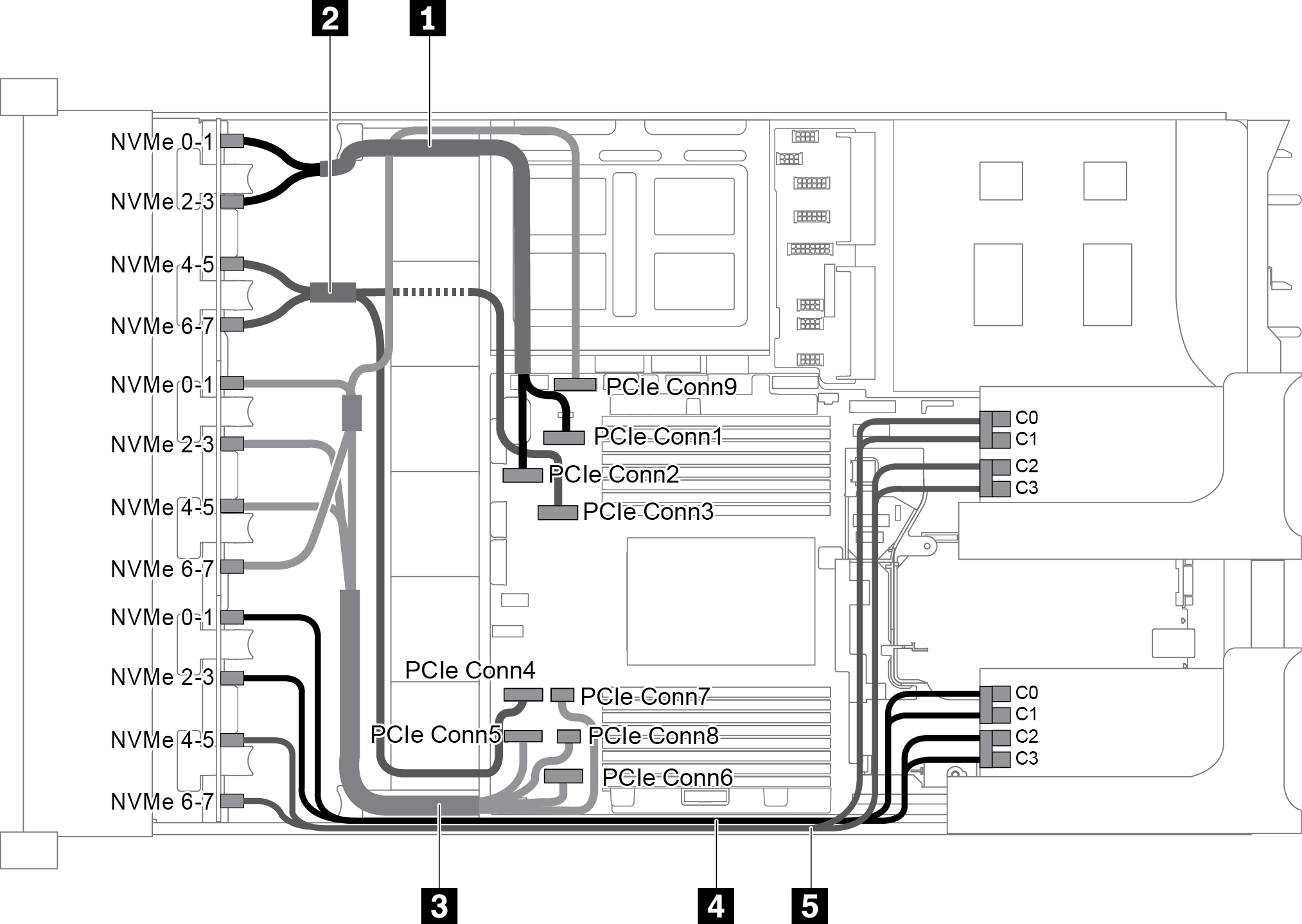
Configuration 1: three 8 x 2.5" NVMe front backplanes, two 810-4P or 1610-4P NVMe switch cards
| Cable | From | To |
|---|---|---|
| 1 NVMe signal cable | NVMe 0-1 connector on the NVMe backplane 1 | PCIe connector 1 on the system board |
| NVMe 2-3 connector on the NVMe backplane 1 | PCIe connector 2 on the system board | |
| 2 NVMe signal cable | NVMe 4-5 connector on the NVMe backplane 1 | PCIe connector 3 on the system board |
| NVMe 6-7 connector on the NVMe backplane 1 | PCIe connector 4 on the system board | |
| 3 NVMe signal cable | NVMe 0-1 connector on the NVMe backplane 2 | PCIe connector 5 on the system board |
| NVMe 2-3 connector on the NVMe backplane 2 | PCIe connector 6 on the system board | |
| NVMe 4-5 connector on the NVMe backplane 2 | PCIe connectors 7 and 8 on the system board | |
| NVMe 6-7 connector on the NVMe backplane 2 | PCIe connector 9 on the system board | |
| 4 NVMe signal cable | NVMe 0-1 connector on the NVMe backplane 3 | Connectors C0 and C1 on the switch card 1 |
| NVMe 2-3 connector on the NVMe backplane 3 | Connectors C2 and C3 on the switch card 1 | |
| 5 NVMe signal cable | NVMe 4-5 connector on the NVMe backplane 3 | Connectors C0 and C1 on the switch card 2 |
| NVMe 6-7 connector on the NVMe backplane 3 | Connectors C2 and C3 on the switch card 2 |
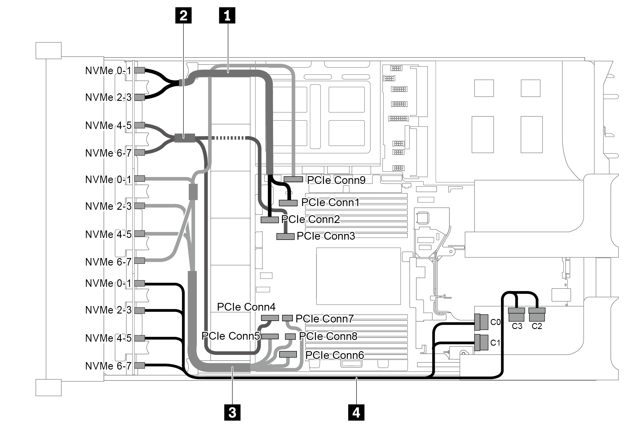
Configuration 2: three 8 x 2.5" NVMe front backplanes, one 1611-8P NVMe switch card
| Cable | From | To |
|---|---|---|
| 1 NVMe signal cable | NVMe 0-1 connector on the NVMe backplane 1 | PCIe connector 1 on the system board |
| NVMe 2-3 connector on the NVMe backplane 1 | PCIe connector 2 on the system board | |
| 2 NVMe signal cable | NVMe 4-5 connector on the NVMe backplane 1 | PCIe connector 3 on the system board |
| NVMe 6-7 connector on the NVMe backplane 1 | PCIe connector 4 on the system board | |
| 3 NVMe signal cable | NVMe 0-1 connector on the NVMe backplane 2 | PCIe connector 5 on the system board |
| NVMe 2-3 connector on the NVMe backplane 2 | PCIe connector 6 on the system board | |
| NVMe 4-5 connector on the NVMe backplane 2 | PCIe connectors 7 and 8 on the system board | |
| NVMe 6-7 connector on the NVMe backplane 2 | PCIe connector 9 on the system board | |
| 4 NVMe signal cable | NVMe 0-1 and 2-3 connectors on the NVMe backplane 3 | Connectors C0 and C1 on the switch card 1 |
| NVMe 4-5 and 6-7 connectors on the NVMe backplane 3 | Connectors C2 and C3 on the switch card 1 |
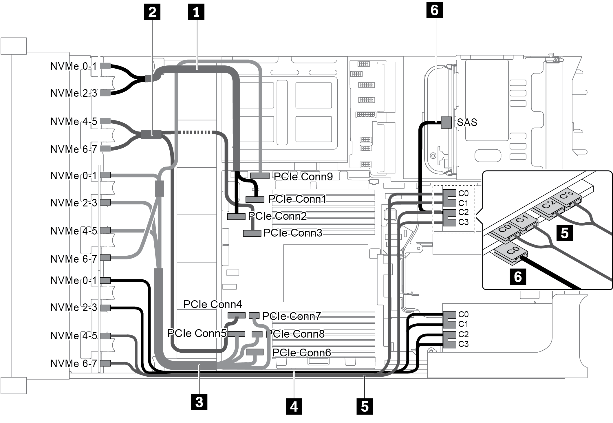
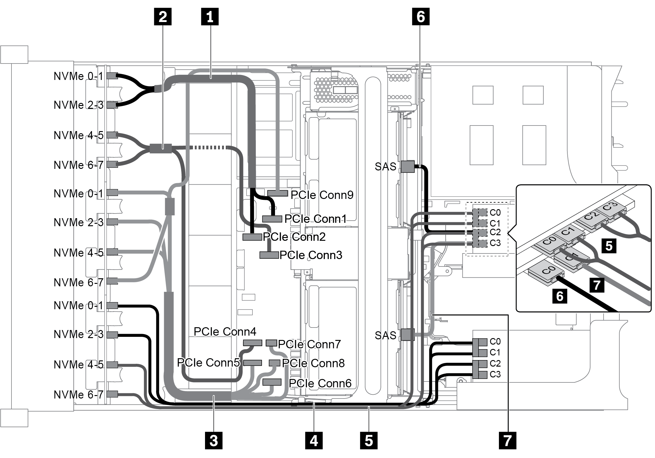
Configuration 3: three 8 x 2.5" NVMe front backplanes, one rear drive cage (SAS/SATA), two 810-4P or 1610–4P NVMe switch cards, one 8i RAID/HBA adapter
This configuration supports one rear drive cage with a 4 x 2.5 SAS/SATA drive backplane.
| Cable | From | To |
|---|---|---|
| 1 NVMe signal cable | NVMe 0-1 connector on the NVMe backplane 1 | PCIe connector 1 on the system board |
| NVMe 2-3 connector on the NVMe backplane 1 | PCIe connector 2 on the system board | |
| 2 NVMe signal cable | NVMe 4-5 connector on the NVMe backplane 1 | PCIe connector 3 on the system board |
| NVMe 6-7 connector on the NVMe backplane 1 | PCIe connector 4 on the system board | |
| 3 NVMe signal cable | NVMe 0-1 connector on the NVMe backplane 2 | PCIe connector 5 on the system board |
| NVMe 2-3 connector on the NVMe backplane 2 | PCIe connector 6 on the system board | |
| NVMe 4-5 connector on the NVMe backplane 2 | PCIe connectors 7 and 8 on the system board | |
| NVMe 6-7 connector on the NVMe backplane 2 | PCIe connector 9 on the system board | |
| 4 NVMe signal cable | NVMe 0-1 connector on the NVMe backplane 3 | Connectors C0 and C1 on the switch card 1 |
| NVMe 2-3 connector on the NVMe backplane 3 | Connectors C2 and C3 on the switch card 1 | |
| 5 NVMe signal cable | NVMe 4-5 connector on the NVMe backplane 3 | Connectors C0 and C1 on the switch card 2 |
| NVMe 6-7 connector on the NVMe backplane 3 | Connectors C2 and C3 on the switch card 2 | |
| 6 SAS signal cable | SAS connector on the rear drive cage | Connector C0 on the 8i RAID/HBA adapter |
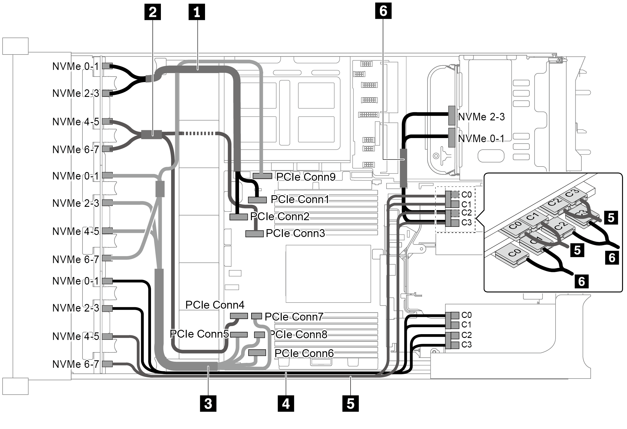
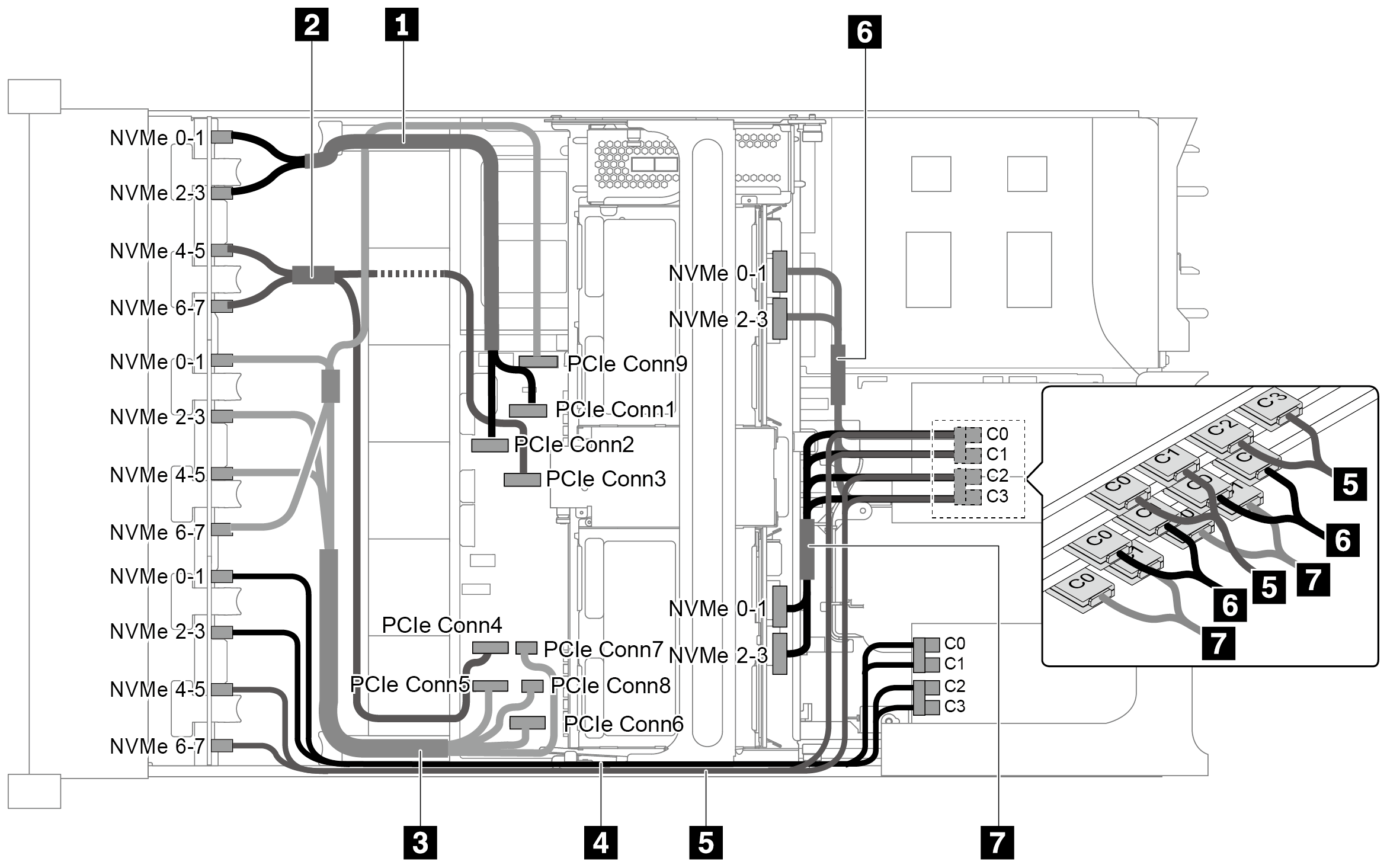
Configuration 4: three 8 x 2.5" NVMe front backplanes, one rear drive cage (NVMe), three 810-4P or 1610–4P NVMe switch cards
This configuration supports one rear drive cage with a 4 x 2.5 NVMe drive backplane.
| Cable | From | To |
|---|---|---|
| 1 NVMe signal cable | NVMe 0-1 connector on the NVMe backplane 1 | PCIe connector 1 on the system board |
| NVMe 2-3 connector on the NVMe backplane 1 | PCIe connector 2 on the system board | |
| 2 NVMe signal cable | NVMe 4-5 connector on the NVMe backplane 1 | PCIe connector 3 on the system board |
| NVMe 6-7 connector on the NVMe backplane 1 | PCIe connector 4 on the system board | |
| 3 NVMe signal cable | NVMe 0-1 connector on the NVMe backplane 2 | PCIe connector 5 on the system board |
| NVMe 2-3 connector on the NVMe backplane 2 | PCIe connector 6 on the system board | |
| NVMe 4-5 connector on the NVMe backplane 2 | PCIe connectors 7 and 8 on the system board | |
| NVMe 6-7 connector on the NVMe backplane 2 | PCIe connector 9 on the system board | |
| 4 NVMe signal cable | NVMe 0-1 connector on the NVMe backplane 3 | Connectors C0 and C1 on the switch card 1 |
| NVMe 2-3 connector on the NVMe backplane 3 | Connectors C2 and C3 on the switch card 1 | |
| 5 NVMe signal cable | NVMe 4-5 connector on the NVMe backplane 3 | Connectors C0 and C1 on the switch card 2 |
| NVMe 6-7 connector on the NVMe backplane 3 | Connectors C2 and C3 on the switch card 2 | |
| 6 NVMe signal cable | NVMe 0-1 connector on the rear NVMe backplane | Connectors C0 and C1 on the switch card 3 |
| NVMe 2-3 connector on the rear NVMe backplane | Connectors C2 and C3 on the switch card 3 |
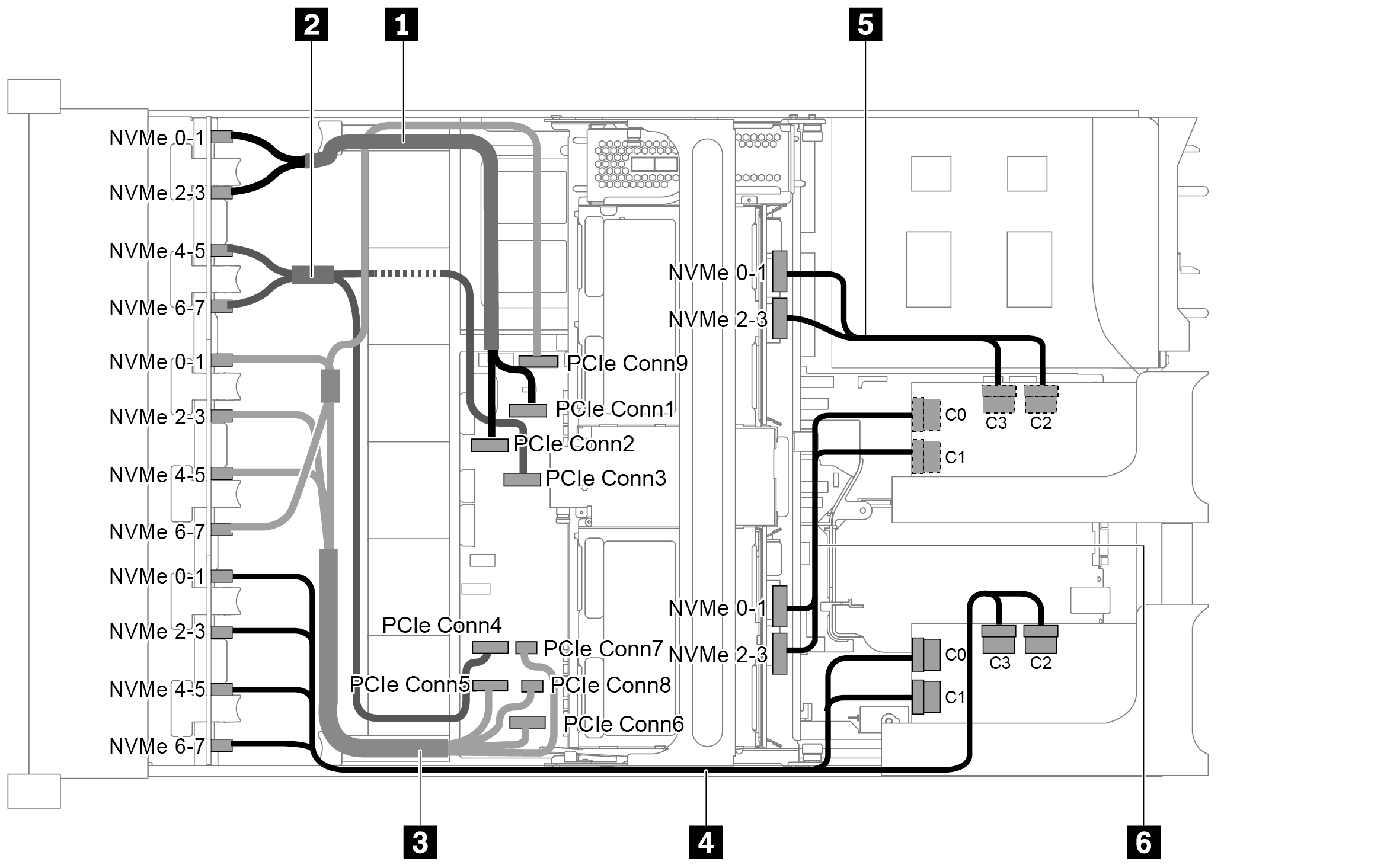
Configuration 5: three 8 x 2.5" NVMe front backplanes, one middle drive cage (SAS/SATA), two 810-4P or 1610–4P NVMe switch cards, one 8i RAID/HBA adapter
This configuration supports one middle 2.5-inch drive cage with two 4 x 2.5-inch SAS/SATA drive backplanes.
When a Gen 4 RAID/HBA adapter is installed, ensure that you use the corresponding Gen 4 cable:
ThinkSystem SR655 2.5" & 3.5" SAS/SATA 4/8-Bay Middle Backplane X40 RAID Cable Kit
| Cable | From | To |
|---|---|---|
| 1 NVMe signal cable | NVMe 0-1 connector on the NVMe backplane 1 | PCIe connector 1 on the system board |
| NVMe 2-3 connector on the NVMe backplane 1 | PCIe connector 2 on the system board | |
| 2 NVMe signal cable | NVMe 4-5 connector on the NVMe backplane 1 | PCIe connector 3 on the system board |
| NVMe 6-7 connector on the NVMe backplane 1 | PCIe connector 4 on the system board | |
| 3 NVMe signal cable | NVMe 0-1 connector on the NVMe backplane 2 | PCIe connector 5 on the system board |
| NVMe 2-3 connector on the NVMe backplane 2 | PCIe connector 6 on the system board | |
| NVMe 4-5 connector on the NVMe backplane 2 | PCIe connectors 7 and 8 on the system board | |
| NVMe 6-7 connector on the NVMe backplane 2 | PCIe connector 9 on the system board | |
| 4 NVMe signal cable | NVMe 0-1 connector on the NVMe backplane 3 | Connectors C0 and C1 on the switch card 1 |
| NVMe 2-3 connector on the NVMe backplane 3 | Connectors C2 and C3 on the switch card 1 | |
| 5 NVMe signal cable | NVMe 4-5 connector on the NVMe backplane 3 | Connectors C0 and C1 on the switch card 2 |
| NVMe 6-7 connector on the NVMe backplane 3 | Connectors C2 and C3 on the switch card 2 | |
| 6 SAS signal cable | SAS connector on the middle backplane 1 | The 8i RAID/HBA adapter
|
| 7 SAS signal cable | SAS connector on the middle backplane 2 | The 8i RAID/HBA adapter
|
Configuration 6: three 8 x 2.5" NVMe front backplanes, one middle drive cage (NVMe), four 810-4P or 1610-4P NVMe switch cards
This configuration supports one middle 2.5-inch drive cage with two 4 x 2.5-inch NVMe drive backplanes.
| Cable | From | To |
|---|---|---|
| 1 NVMe signal cable | NVMe 0-1 connector on the NVMe backplane 1 | PCIe connector 1 on the system board |
| NVMe 2-3 connector on the NVMe backplane 1 | PCIe connector 2 on the system board | |
| 2 NVMe signal cable | NVMe 4-5 connector on the NVMe backplane 1 | PCIe connector 3 on the system board |
| NVMe 6-7 connector on the NVMe backplane 1 | PCIe connector 4 on the system board | |
| 3 NVMe signal cable | NVMe 0-1 connector on the NVMe backplane 2 | PCIe connector 5 on the system board |
| NVMe 2-3 connector on the NVMe backplane 2 | PCIe connector 6 on the system board | |
| NVMe 4-5 connector on the NVMe backplane 2 | PCIe connectors 7 and 8 on the system board | |
| NVMe 6-7 connector on the NVMe backplane 2 | PCIe connector 9 on the system board | |
| 4 NVMe signal cable | NVMe 0-1 connector on the NVMe backplane 3 | Connectors C0 and C1 on the switch card 1 |
| NVMe 2-3 connector on the NVMe backplane 3 | Connectors C2 and C3 on the switch card 1 | |
| 5 NVMe signal cable | NVMe 4-5 connector on the NVMe backplane 3 | Connectors C0 and C1 on the switch card 2 |
| NVMe 6-7 connector on the NVMe backplane 3 | Connectors C2 and C3 on the switch card 2 | |
| 6 NVMe signal cable | NVMe 0-1 connector on the middle backplane 1 | Connectors C0 and C1 on the switch card 3 |
| NVMe 2-3 connector on the middle backplane 1 | Connectors C2 and C3 on the switch card 3 | |
| 7 SAS signal cable | NVMe 0-1 connector on the middle backplane 2 | Connectors C0 and C1 on the switch card 4 |
| NVMe 2-3 connector on the middle backplane 2 | Connectors C2 and C3 on the switch card 4 |
Configuration 7: three 8 x 2.5" NVMe front backplanes, one middle drive cage (NVMe), two 1611-8P NVMe switch cards
This configuration supports one middle 2.5-inch drive cage with two 4 x 2.5-inch NVMe drive backplanes.
| Cable | From | To |
|---|---|---|
| 1 NVMe signal cable | NVMe 0-1 connector on the NVMe backplane 1 | PCIe connector 1 on the system board |
| NVMe 2-3 connector on the NVMe backplane 1 | PCIe connector 2 on the system board | |
| 2 NVMe signal cable | NVMe 4-5 connector on the NVMe backplane 1 | PCIe connector 3 on the system board |
| NVMe 6-7 connector on the NVMe backplane 1 | PCIe connector 4 on the system board | |
| 3 NVMe signal cable | NVMe 0-1 connector on the NVMe backplane 2 | PCIe connector 5 on the system board |
| NVMe 2-3 connector on the NVMe backplane 2 | PCIe connector 6 on the system board | |
| NVMe 4-5 connector on the NVMe backplane 2 | PCIe connectors 7 and 8 on the system board | |
| NVMe 6-7 connector on the NVMe backplane 2 | PCIe connector 9 on the system board | |
| 4 NVMe signal cable | NVMe 0-1 and 2-3 connectors on the NVMe backplane 3 | Connectors C0 and C1 on the switch card 1 in PCIe slot 1 |
| NVMe 4-5 and 6-7 connectors on the NVMe backplane 3 | Connectors C2 and C3 on the switch card 1 in PCIe slot 1 | |
| 5 NVMe signal cable | NVMe 0-1 and 2-3 connectors on the middle backplane 1 | Connectors C0 and C1 on the switch card 2 in PCIe slot 5 |
| 6 NVMe signal cable | NVMe 0-1 and 2-3 connectors on the middle backplane 2 | Connectors C2 and C3 on the switch card 2 in PCIe slot 5 |