Front I/O assembly
The front I/O assembly of the server provides controls, connectors, and LEDs. The front I/O assembly varies by model.
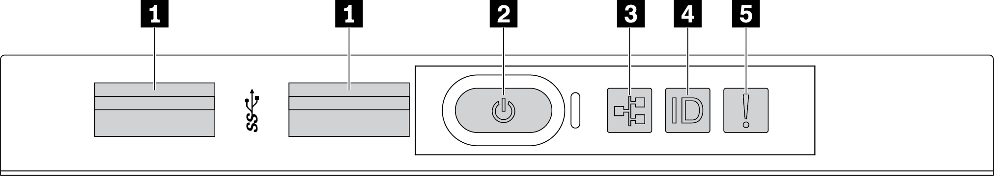
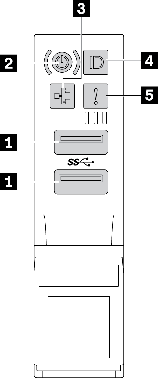
| Callout | Callout |
|---|---|
| 1 USB 3.1 connectors | 2 Power button with power status LED |
| 3 Network activity LED (for OCP 3.0 Ethernet adapter) | 4 System ID button with system ID LED |
| 5 System error LED |
1 USB 3.1 connectors
Used to attach a device that requires a USB 2.0 or 3.1 connection, such as a keyboard, a mouse, or a USB storage device.
2 Power button with power status LED
| Status | Color | Description |
|---|---|---|
| Solid on | Green | The server is on and running. |
| Slow blinking (about one flash per second) | Green | The server is off and is ready to be powered on (standby state). |
| Off | None | There is no ac power applied to the server. |
3 Network activity LED
When an OCP 3.0 Ethernet adapter is installed, the network activity LED on the front I/O assembly helps you identify the network connectivity and activity.
| Status | Color | Description |
|---|---|---|
| On | Green | The server is connected to a network. |
| Blinking | Green | The network is connected and active. |
| Off | None | The server is disconnected from the network. |
4 System ID button with system ID LED
Use this system ID button and the blue system ID LED to visually locate the server. A system ID LED is also located on the rear of the server. Each time you press the system ID button, the state of both the system ID LEDs changes. The LEDs can be changed to on, blinking, or off.
5 System error LED
The system error LED provides basic diagnostic functions for your server. If the system error LED is lit, one or more LEDs elsewhere in the server might also be lit to direct you to the source of the error.
| Status | Color | Description | Action |
|---|---|---|---|
| On | Yellow | An error has been detected on the server. Causes might include but not limited to the following errors:
| Check the event log to determine the exact cause of the error. Alternatively, follow the light path diagnostics to determine if additional LEDs are lit that will direct you to identify the cause of the error. |
| Off | None | The server is off or the server is on and is working correctly. | None. |