System board components
The illustration in this section shows the component locations on the system board.
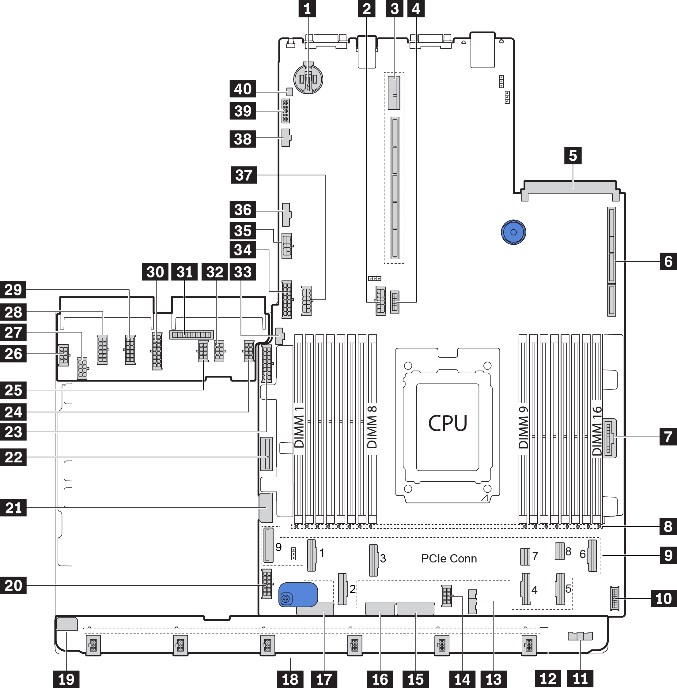
| 1 CMOS battery | 2 Rear backplane power connector |
| 3 Riser 2 slot | 4 Front VGA connector |
| 5 OCP Ethernet adapter slot | 6 Riser 1 slot |
| 7 Front panel connector | 8 DIMM 1-16 error LEDs |
| 9 PCIe connectors* | 10 Front USB connector |
| 11 Fan board sideband connector (connect to 13) | 12 Fan 1-6 error LEDs |
| 13 Fan board sideband connector (connect to 11) | 14 CPU power connector (connect to 27) |
| 15 Front backplane power connector* | 16 System power connector 3 (connect to 28) |
| 17 Front backplane power connector* | 18 Fan 1-6 connectors |
| 19 Fan board power connector (connect to 26) | 20 System board power connector 2 (connect to 29) |
| 21 Middle 2.5-inch-drive backplane 1 power connector | 22 Internal riser power connector |
| 23 Front 2.5-inch-drive backplane 1 power connector | 24 GPU power connector 1 |
| 25 GPU power connector 3 | 26 Fan board power connector (connect to 19) |
| 27 CPU power connector (connect to 14) | 28 System power connector 3 (connect to 16) |
| 29 System power connector 2 (connect to 20) | 30 System power connector 1 (connect to 34) |
| 31 PIB sideband connector (connect to 36) | 32 GPU power connector 2 |
| 33 M.2 sideband connector | 34 System power connector 1 (connect to 30) |
| 35 Riser 3 power connector | 36 PIB sideband connector (connect to 31) |
| 37 Middle backplane power connector* | 38 Riser 3 sideband connector |
| 39 TPM adapter connector (for Chinese Mainland only) | 40 Intrusion switch connector |
9: The PCIe connectors are connected to NVMe backplanes, M.2 adapter, riser cards, or SAS/SATA backplanes. For detailed information, see Internal cable routing.
- 15:
Front 2.5-inch-drive backplane 3 power connector when three front 2.5-inch-drive backplanes are installed.
Front 3.5-inch-drive backplane power connector 2 when the 12 x 3.5-inch-drive backplane is installed.
- 17:
Front 2.5-inch-drive backplane 2 power connector when two front 2.5-inch-drive backplanes are installed.
Front 3.5-inch-drive backplane power connector 1 when the 12 x 3.5-inch-drive backplane or 8 x 3.5-inch-drive backplane is installed.
- 37:
Middle 2.5-inch-drive backplane 2 power connector when the middle 2.5-inch-drive cage is installed.
Middle 3.5-inch-drive backplane power connector when the middle 3.5-inch-drive cage is installed.