Front view
The front view of the server varies by model.
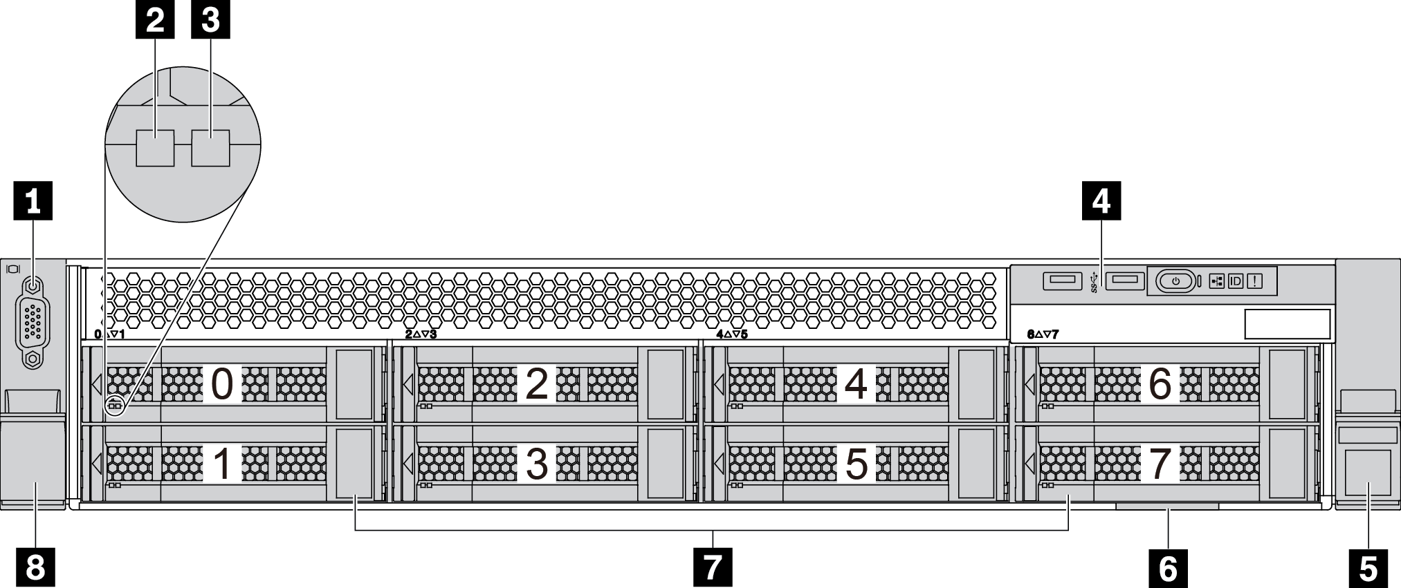
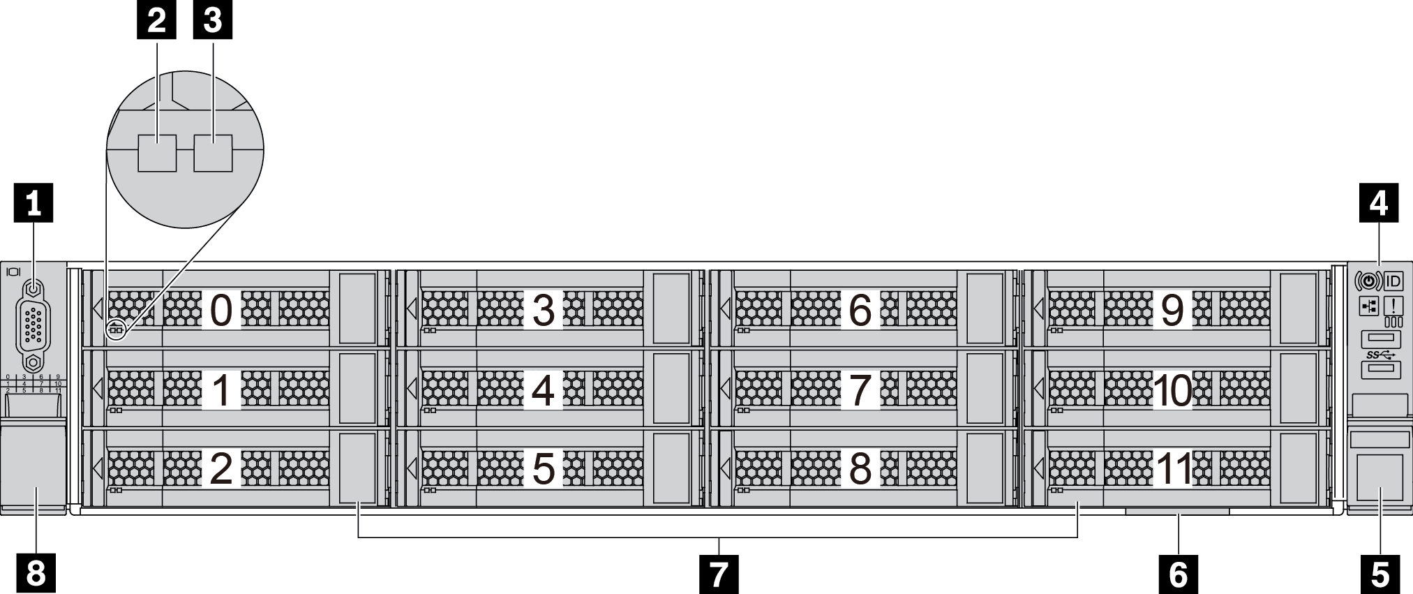
Front views of server models with 2.5-inch drive bays
The following illustrations show the front views of server models with 2.5-inch drive bays.
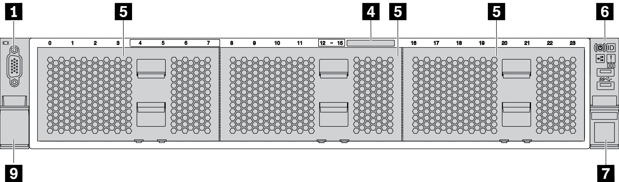
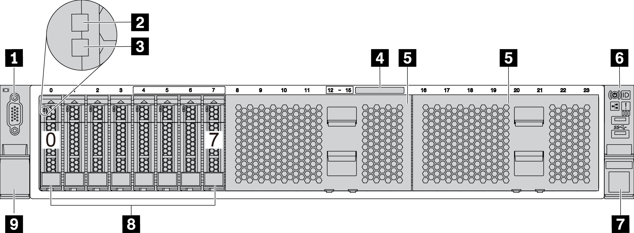
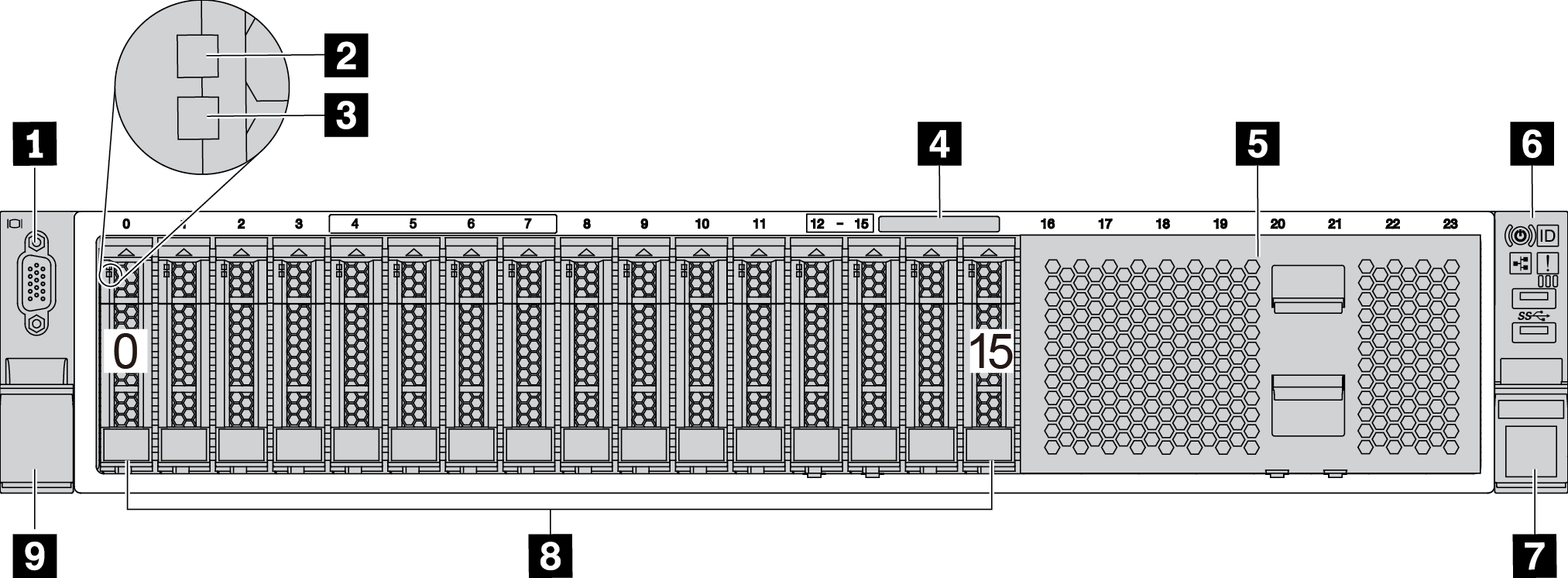
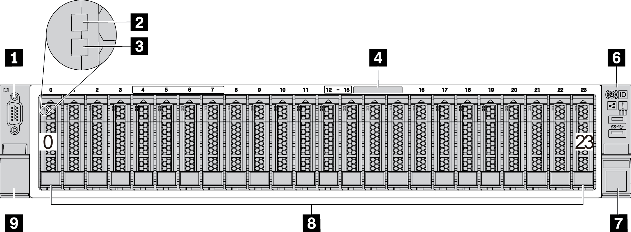
| Callout | Callout |
|---|---|
| 1 VGA connector (optional) | 2 Drive activity LED |
| 3 Drive status LED | 4 Pull-out information tab |
| 5 Drive bay filler (8-bay filler) | 6 Front I/O assembly |
| 7 Rack latch (right) | 8 Drive bays |
| 9 Rack latch (left) |
1 VGA connector (optional)
Used to attach a high-performance monitor, a direct-drive monitor, or other devices that use a VGA connector.
2 Drive activity LED
3 Drive status LED
| Drive LED | Status | Description |
|---|---|---|
| Drive activity LED | Solid green | The drive is powered but not active. |
| Blinking green | The drive is active. | |
| Drive status LED | Solid yellow | The drive has an error. |
| Blinking yellow (blinking slowly, about one flash per second) | The drive is being rebuilt. | |
| Blinking yellow (blinking rapidly, about four flashes per second) | The RAID adapter is locating the drive. |
4 Pull-out information tab
A label on the tab shows the network information (MAC address and other data) to remotely access the service processor.
5 Drive bay filler
The drive bay filler is used to cover vacant drive bays.
6 Front I/O assembly
For information about the controls, connectors, and status LEDs on the front I/O assembly, see Front I/O assembly.
7 9 Rack latches
If your server is installed in a rack, you can use the rack latches to help you slide the server out of the rack. You also can use the rack latches and screws to secure the server in the rack so that the server cannot slide out, especially in vibration-prone areas. For more information, refer to the Rack Installation Guide that comes with your rail kit.
8 Drive bays
The number of the installed drives in your server varies by model. When you install drives, follow the order of the drive bay numbers.
The EMI integrity and cooling of the server are protected by having all drive bays occupied. The vacant drive bays must be occupied by drive bay fillers or drive fillers.
Front views of server models with 3.5-inch drive bays
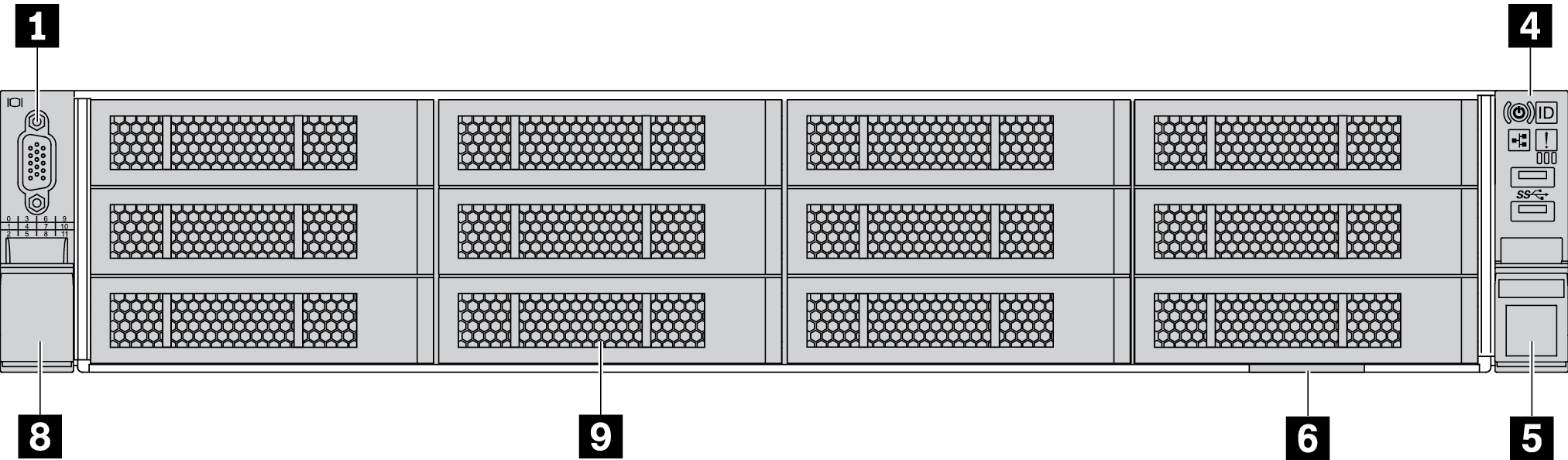
| Callout | Callout |
|---|---|
| 1 VGA connector (optional) | 2 Drive activity LED |
| 3 Drive status LED | 4 Front I/O assembly |
| 5 Rack latch (right) | 6 Pull-out information tab |
| 7 Drive bays | 8 Rack latch (left) |
| 9 Drive bay filler |
1 VGA connector (optional)
Used to attach a high-performance monitor, a direct-drive monitor, or other devices that use a VGA connector.
2 Drive activity LED
3 Drive status LED
| Drive LED | Status | Description |
|---|---|---|
| Drive activity LED | Solid green | The drive is powered but not active. |
| Blinking green | The drive is active. | |
| Drive status LED | Solid yellow | The drive has an error. |
| Blinking yellow (blinking slowly, about one flash per second) | The drive is being rebuilt. | |
| Blinking yellow (blinking rapidly, about four flashes per second) | The RAID adapter is locating the drive. |
4 Front I/O assembly
For information about the controls, connectors, and status LEDs on the front I/O assembly, see Front I/O assembly.
5 8 Rack latches
If your server is installed in a rack, you can use the rack latches to help you slide the server out of the rack. You also can use the rack latches and screws to secure the server in the rack so that the server cannot slide out, especially in vibration-prone areas. For more information, refer to the Rack Installation Guide that comes with your rail kit.
6 Pull-out information tab
A label on the tab shows the network information (MAC address and other data) to remotely access the service processor.
7 Drive bays
The number of the installed drives in your server varies by model. When you install drives, follow the order of the drive bay numbers.
The EMI integrity and cooling of the server are protected by having all drive bays occupied. The vacant drive bays must be occupied by drive bay fillers or drive fillers.
9 Drive bay filler
The drive bay filler is used to cover vacant drive bays.