Server model with 16 x 2.5-inch front drive bays (NVMe)
This section provides cable routing information for the server model with two 8 x 2.5-inch NVMe front backplanes.
Configuration 1: two 8 x 2.5" NVMe front backplanes, onboard connections
Figure 1. Cable routing for configuration with two 8 x 2.5" NVMe front backplanes
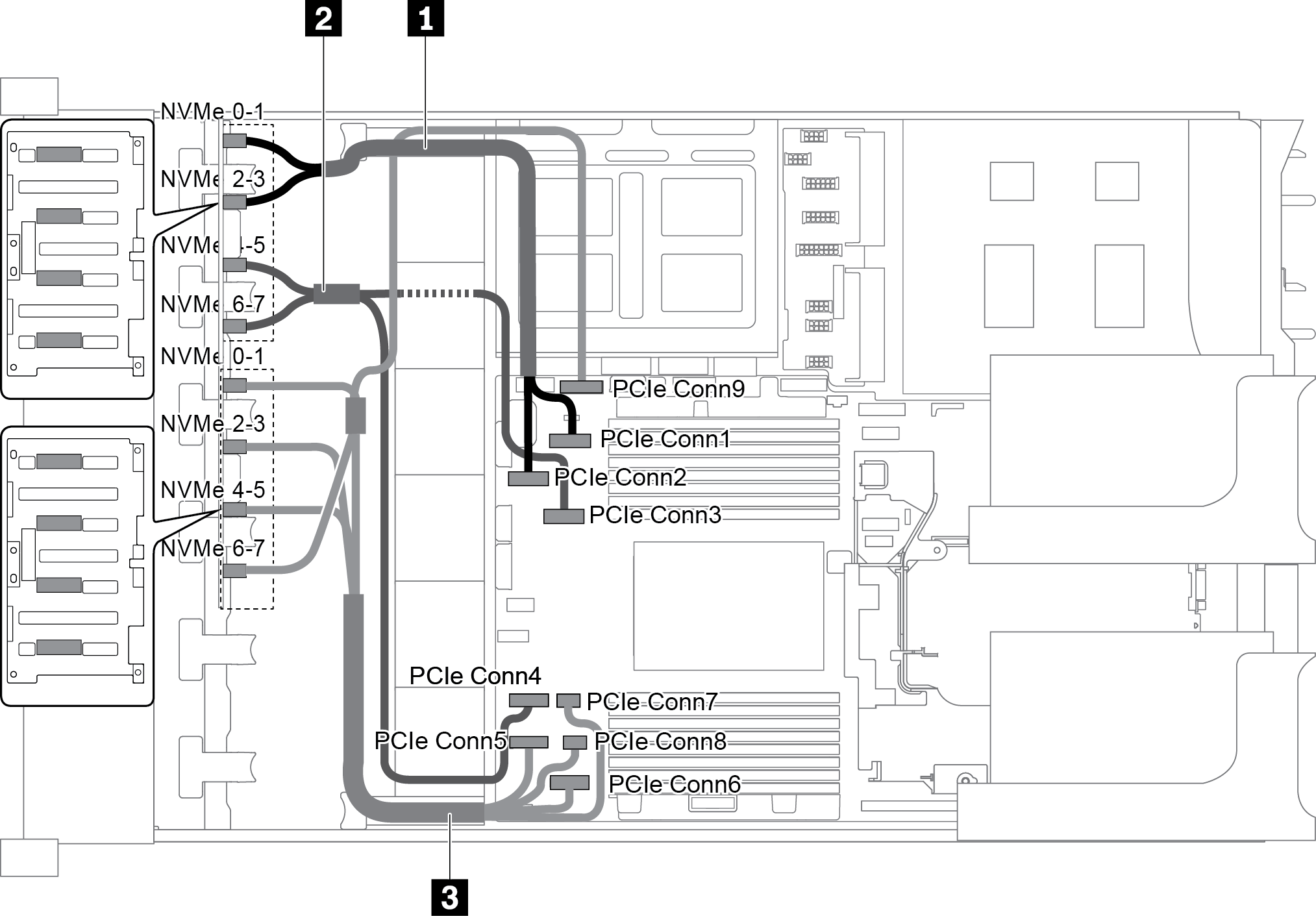
| Cable | From | To |
|---|---|---|
| 1 NVMe signal cable | NVMe 0-1 connector on backplane 1 | PCIe connector 1 on the system board |
| NVMe 2-3 connector on backplane 1 | PCIe connector 2 on the system board | |
| 2 NVMe signal cable | NVMe 4-5 connector on backplane 1 | PCIe connector 3 on the system board |
| NVMe 6-7 connector on backplane 1 | PCIe connector 4 on the system board | |
| 3 NVMe signal cable | NVMe 0-1 connector on backplane 2 | PCIe connector 5 on the system board |
| NVMe 2-3 connector on backplane 2 | PCIe connector 6 on the system board | |
| NVMe 4-5 connector on backplane 2 | PCIe connectors 7 and 8 on the system board | |
| NVMe 6-7 connector on backplane 2 | PCIe connector 9 on the system board |
Configuration 2: two 8 x 2.5" NVMe front backplanes, one rear drive cage (SAS/SATA), one 8i RAID/HBA adapter
This configuration supports one rear drive cage with the 4 x 2.5-inch SAS/SATA drive backplane.
Note
The RAID/HBA adapter can be installed on riser card 1 (scenario 1) or riser card 2 (scenario 2). The following illustration shows the cable connections for scenario 1. The cable connections are the same for scenario 2.
Figure 2. Cable routing for configuration with two 8 x 2.5" NVMe front backplanes, one rear drive cage (SAS/SATA), one 8i RAID/HBA adapter
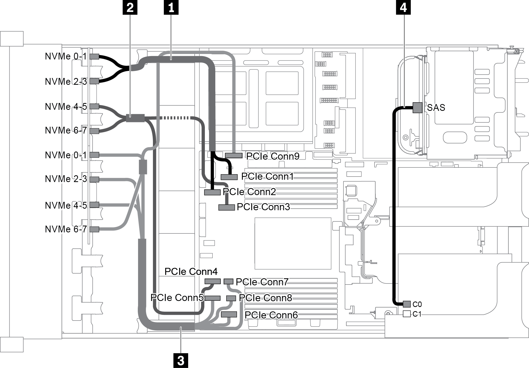
| Cable | From | To |
|---|---|---|
| 1 NVMe signal cable | NVMe 0-1 connector on backplane 1 | PCIe connector 1 on the system board |
| NVMe 2-3 connector on backplane 1 | PCIe connector 2 on the system board | |
| 2 NVMe signal cable | NVMe 4-5 connector on backplane 1 | PCIe connector 3 on the system board |
| NVMe 6-7 connector on backplane 1 | PCIe connector 4 on the system board | |
| 3 NVMe signal cable | NVMe 0-1 connector on backplane 2 | PCIe connector 5 on the system board |
| NVMe 2-3 connector on backplane 2 | PCIe connector 6 on the system board | |
| NVMe 4-5 connector on backplane 2 | PCIe connectors 7 and 8 on the system board | |
| NVMe 6-7 connector on backplane 2 | PCIe connector 9 on the system board | |
| 4 SAS signal cable | SAS connector on the rear backplane | Connector C0 on the RAID/HBA adapter |
Configuration 3: two 8 x 2.5" NVMe front backplanes, one rear drive cage (NVMe), one 810-4P or 1610–4P NVMe switch card
This configuration supports one rear drive cage with the 4 x 2.5-inch NVMe drive backplane.
Figure 3. Cable routing for configuration with two 8 x 2.5" NVMe front backplanes, one rear drive cage (NVMe), and one 810-4P or 1610-4P NVMe switch card
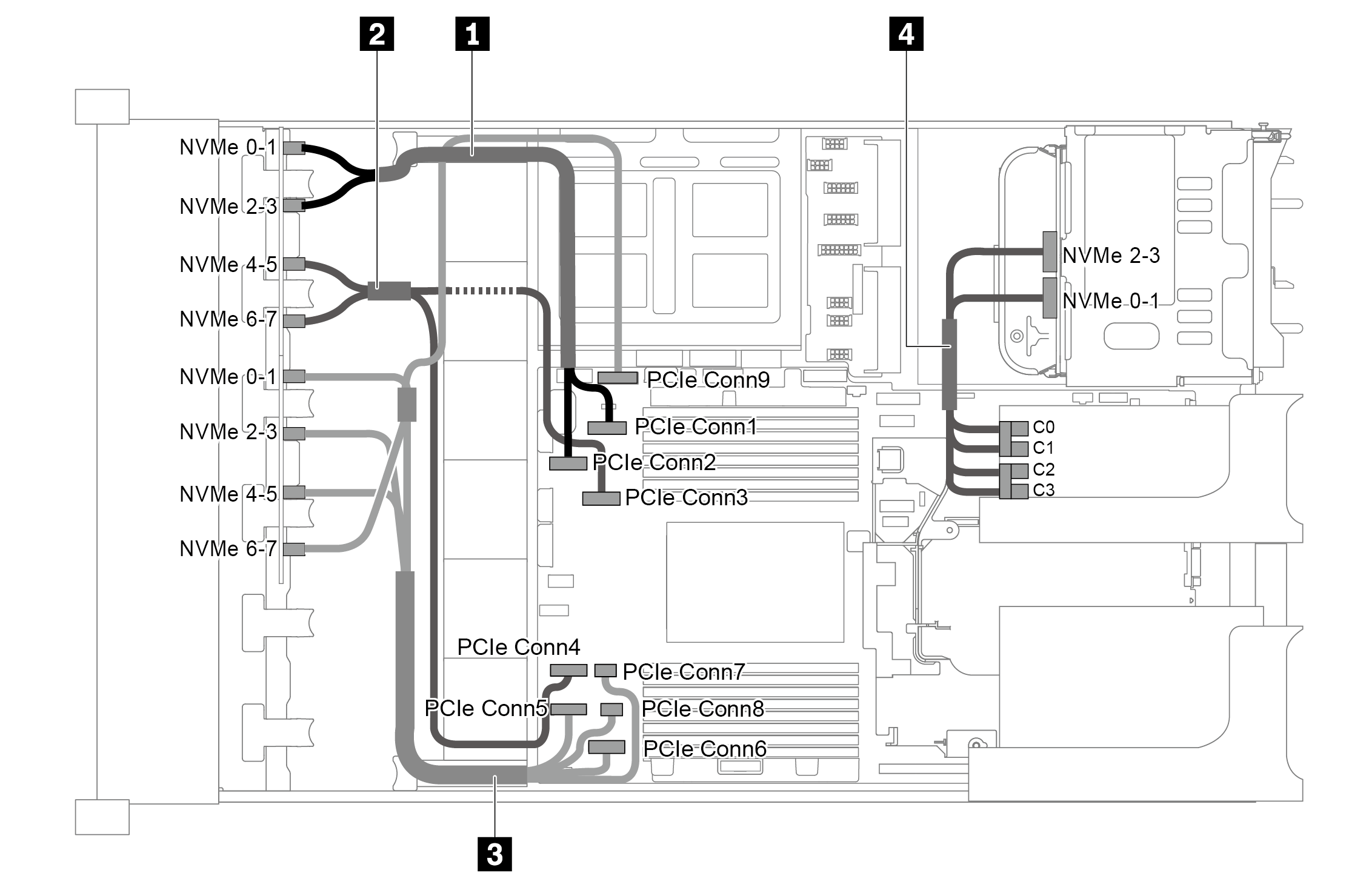
| Cable | From | To |
|---|---|---|
| 1 NVMe signal cable | NVMe 0-1 connector on backplane 1 | PCIe connector 1 on the system board |
| NVMe 2-3 connector on backplane 1 | PCIe connector 2 on the system board | |
| 2 NVMe signal cable | NVMe 4-5 connector on backplane 1 | PCIe connector 3 on the system board |
| NVMe 6-7 connector on backplane 1 | PCIe connector 4 on the system board | |
| 3 NVMe signal cable | NVMe 0-1 connector on backplane 2 | PCIe connector 5 on the system board |
| NVMe 2-3 connector on backplane 2 | PCIe connector 6 on the system board | |
| NVMe 4-5 connector on backplane 2 | PCIe connectors 7 and 8 on the system board | |
| NVMe 6-7 connector on backplane 2 | PCIe connector 9 on the system board | |
| 4 NVMe signal cable | NVMe 0-1 connector on the rear backplane | Connectors C0 and C1 on the switch card |
| NVMe 2-3 connector on the rear backplane | Connectors C2 and C3 on the switch card |
Give documentation feedback