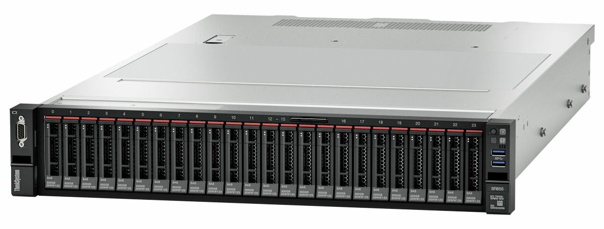
ThinkSystem SR655 (7Y00, 7Z01)
The ThinkSystem™ SR655 server (machine type: 7Y00, 7Z01) is a 1-socket 2U server that features the new AMD EPYC 7002 family of processors. The server offers a broad selection of drive and slot configurations and offers high performance and expansion for various IT workloads. Combining performance and flexibility, the server is a great choice for enterprises of all sizes.
- Resources and downloads
This section provides handy documents, driver and firmware downloads, and support resources. - Server package contents
When you receive your server, verify that the shipment contains everything that you expected to receive. - Features
Performance, ease of use, reliability, and expansion capabilities were key considerations in the design of the server. These design features make it possible for you to customize the system hardware to meet your needs today and provide flexible expansion capabilities for the future. - Specifications
The following information is a summary of the features and specifications of the server. Depending on the model, some features might not be available, or some specifications might not apply. - Management options
The XClarity portfolio and other system management offerings described in this section are available to help you manage the servers more conveniently and efficiently. - Server components
This section provides information to help you locate your server components. - Server hardware setup
To set up the server, install any options that have been purchased, cable the server, configure and update the firmware, and install the operating system. - System configuration
Complete these procedures to configure your system. - Hardware replacement procedures
This section provides installation and removal procedures for all serviceable system components. Each component replacement procedure references any tasks that need to be performed to gain access to the component being replaced. - Problem determination
Use the information in this section to isolate and resolve issues that you might encounter while using your server. - Messages
When attempting to resolve issues with your server, the best practice is to begin with the event log of the application that is managing the server. - Tech Tips
Lenovo continually updates the support Web site with the latest tips and techniques that you can use to solve issues that you might have with your server. These Tech Tips (also called retain tips or service bulletins) provide procedures to work around issues related to the operation of your server. - Security advisories
Lenovo is committed to developing products and services that adhere to the highest security standards in order to protect our customers and their data. When potential vulnerabilities are reported, it is the responsibility of the Lenovo Product Security Incident Response Team (PSIRT) to investigate and provide information to our customers so they may put mitigation plans in place as we work toward providing solutions. - Hardware disassembling for recycle
Follow the instructions in this section to recycle components with compliance with local laws or regulations. - Getting help and technical assistance
If you need help, service, or technical assistance or just want more information about Lenovo products, you will find a wide variety of sources available from Lenovo to assist you.
Give documentation feedback