Rear view
The rear of the server provides access to several connectors and components.
Server models with eight PCIe slots
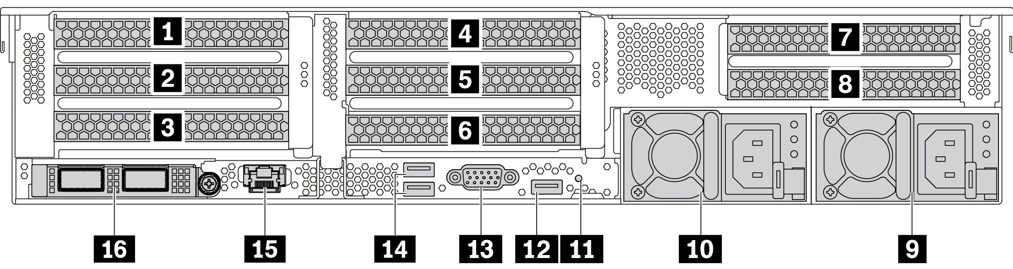
| Callout | Callout |
|---|---|
| 1 PCIe slot 1 (on riser 1 assembly) | 2 PCIe slot 2 (on riser 1 assembly) |
| 3 PCIe slot 3 (on riser 1 assembly) | 4 PCIe slot 4 (on riser 2 assembly) |
| 5 PCIe slot 5 (on riser 2 assembly) | 6 PCIe slot 6 (on riser 2 assembly) |
| 7 PCIe slot 7 (on riser 3 assembly) | 8 PCIe slot 8 (on riser 3 assembly) |
| 9 Power supply 1 | 10 Power supply 2 (optional) |
| 11 NMI button | 12 USB 3.2 Gen 1 (5 Gbps) connector (1 DCI) |
| 13 VGA connector | 14 USB 3.2 Gen 1 (5 Gbps) connectors (2 DCIs) |
| 15 XClarity Controller Network connector | 16 Ethernet connectors on OCP 3.0 Ethernet adapter (optional, two or four connectors may be available) |
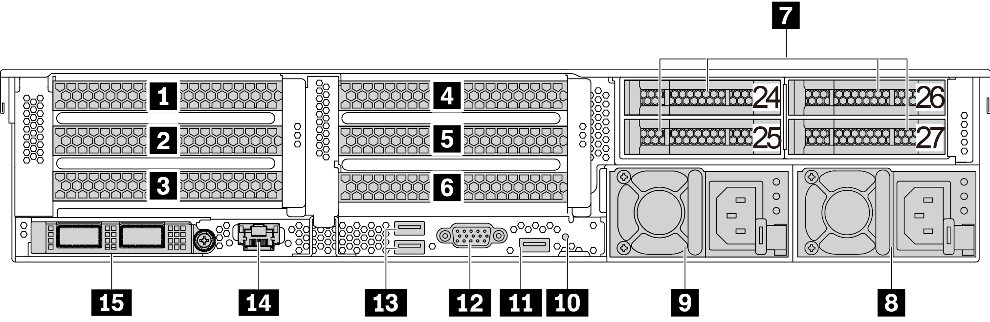
Server models with four 2.5-inch rear drive bays and six PCIe slots
| Callout | Callout |
|---|---|
| 1 PCIe slot 1 (on riser 1 assembly) | 2 PCIe slot 2 (on riser 1 assembly) |
| 3 PCIe slot 3 (on riser 1 assembly) | 4 PCIe slot 4 (on riser 2 assembly) |
| 5 PCIe slot 5 (on riser 2 assembly) | 6 PCIe slot 6 (on riser 2 assembly) |
| 7 2.5-inch rear drive bays (4) | 8 Power supply 1 |
| 9 Power supply 2 (optional) | 10 NMI button |
| 11 USB 3.2 Gen 1 (5 Gbps) connector (1 DCI) | 12 VGA connector |
| 13 USB 3.2 Gen 1 (5 Gbps) connectors (2 DCIs) | 14 XClarity Controller Network connector |
| 15 Ethernet connectors on OCP 3.0 Ethernet adapter (optional, two or four connectors may be available) |
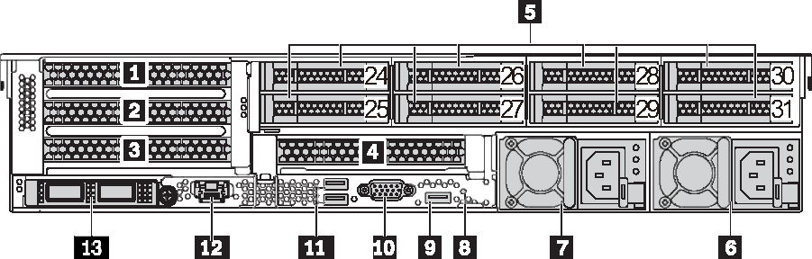
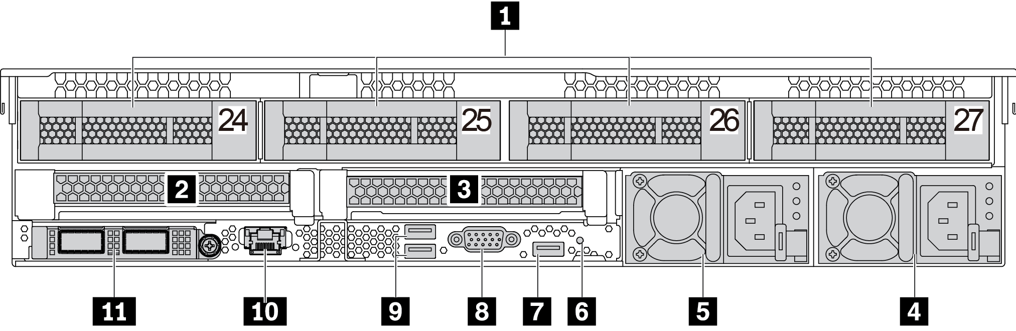
Server models with eight 2.5-inch rear drive bays and four PCIe slots
| Callout | Callout |
|---|---|
| 1 PCIe slot 1 (on riser 1 assembly) | 2 PCIe slot 2 (on riser 1 assembly) |
| 3 PCIe slot 3 (on riser 1 assembly) | 4 PCIe slot 6 (on riser 2 assembly) |
| 5 2.5-inch rear drive bays (8) | 6 Power supply 1 |
| 7 Power supply 2 (optional) | 8 NMI button |
| 9 USB 3.2 Gen 1 (5 Gbps) connector (1 DCI) | 10 VGA connector |
| 11 USB 3.2 Gen 1 (5 Gbps) connectors (2 DCIs) | 12 XClarity Controller Network connector |
| 13 Ethernet connectors on OCP 3.0 Ethernet adapter (optional, two or four connectors may be available) |
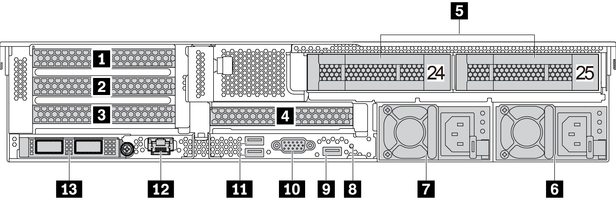
Server models with two 3.5-inch rear drive bays and four PCIe slots
| Callout | Callout |
|---|---|
| 1 PCIe slot 1 (on riser 1 assembly) | 2 PCIe slot 2 (on riser 1 assembly) |
| 3 PCIe slot 3 (on riser 1 assembly) | 4 PCIe slot 6 (on riser 2 assembly) |
| 5 3.5-inch rear drive bays (2) | 6 Power supply 1 |
| 7 Power supply 2 (optional) | 8 NMI button |
| 9 USB 3.2 Gen 1 (5 Gbps) connector (1 DCI) | 10 VGA connector |
| 11 USB 3.2 Gen 1 (5 Gbps) connectors (2 DCIs) | 12 XClarity Controller Network connector |
| 13 Ethernet connectors on OCP 3.0 Ethernet adapter (optional, two or four connectors may be available) |
Server models with four 3.5-inch rear drive bays and two PCIe slots
| Callout | Callout |
|---|---|
| 1 3.5-inch rear drive bays (4) | 2 PCIe slot 3 (on riser 1 assembly) |
| 3 PCIe slot 6 (on riser 2 assembly) | 4 Power supply 1 |
| 5 Power supply 2 (optional) | 6 NMI button |
| 7 USB 3.2 Gen 1 (5 Gbps) connector (1 DCI) | 8 VGA connector |
| 9 USB 3.2 Gen 1 (5 Gbps) connectors (2 DCIs) | 10 XClarity Controller Network connector |
| 11 Ethernet connectors on OCP 3.0 Ethernet adapter (optional, two or four connectors may be available) |
Rear components overview
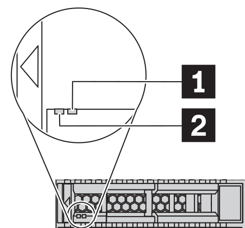
Drive LEDs
Each hot-swap drive comes with an activity LED and status LED and the signals are controlled by the backplanes. Different colors and speeds indicate different activities or status of the drive. The following illustrates the LEDs on a Hard disk drive or solid–state drive.
| Drive LED | Status | Description |
|---|---|---|
| 1 Drive status LED (right) | Solid yellow | The drive has an error. |
| Blinking yellow (blinking slowly, about one flash per second) | The drive is being rebuilt. | |
| Blinking yellow (blinking rapidly, about four flashes per second) | The RAID adapter is locating the drive. | |
| 2 Drive activity LED (left) | Solid green | The drive is powered but not active. |
| Blinking green | The drive is active. |
Ethernet connectors
Figure 2. OCP module (two connectors) 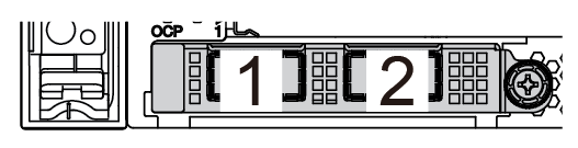 | Figure 3. OCP module (four connectors) 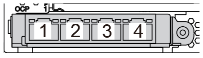 |
Note
| |
Hot-swap drives and drive bays
The drive bays on the front and rear of your server are designed for hot-swap drives. The number of the installed drives in your server varies by model. When you install drives, follow the order of the drive bay numbers.
The EMI integrity and cooling of the server are protected by having all drive bays occupied. Vacant drive bays must be occupied by drive fillers.
PCIe slots
The PCIe slots are on the rear of the server and your server supports up to eight PCIe slots on riser 1, 2, and 3 assemblies. For more information about the PCIe slots, see PCIe slots and configurations.
COM cable (slot 3 or 6 only)
Fiber channel HBA adapters
GPU adapters
RAID/HBA adapters
Network adapters
NVMe switch adapter
7mm-thick 2.5-inch SSDs (slot 3 or 6 only)
PCIe SSDs
Power supplies
The hot-swap redundant power supply helps you avoid significant interruption to the operation of the system when a power supply fails. You can purchase a power supply option from Lenovo and install the power supply to provide power redundancy without turning off the server.
On each power supply, there are three status LEDs near the power cord connector. For information about the LEDs, see Rear view LEDs.
USB 3.2 Gen 1 (5 Gbps) connectors
The USB 3.2 Gen 1 (5 Gbps) connectors can be used to attach a USB-compatible device, such as a USB keyboard, USB mouse, or USB storage device.
VGA connector
The VGA connectors on the front and rear of the server can be used to attach a high-performance monitor, a direct-drive monitor, or other devices that use a VGA connector.
XClarity Controller network connector
The XClarity Controller network connector can be used to attach an Ethernet cable to manage the baseboard management controller (BMC).