Remove the I/O expansion cage
Use this information to remove the I/O riser cage.
Power off the server. See Power off the server.
Disconnect power cords from both power supplies, which are located in the rear of the server.
Record the location of the cables in the front of the PCIe adapters that are installed in the I/O expansion cage at the front of the server, and disconnect the cables.
Disconnect the management port cable from the management port in the I/O expansion cage, if necessary.
Loosen the two captive screws located on the front of the server. If necessary, use a P2 screwdriver to loosen the screws.
Loosen the two captive screws located on the front of the server using a P2 screwdriver.
Pull the server forward until the slide rails click into place.
Remove the top cover. See Remove the top cover.
Remove the air baffle. See Remove the air baffle.
Remove the system fan cage. See Remove the system fan cage.
NoteYou do not need to completely remove the system fan cage. Instead, after removing the system fan cage, carefully place it on the drive cage to get the system fan cage out of the way.
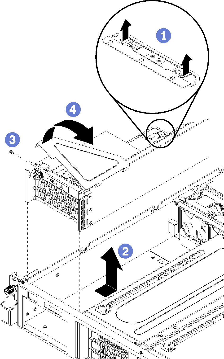
To remove the I/O expansion cage, complete the following steps:
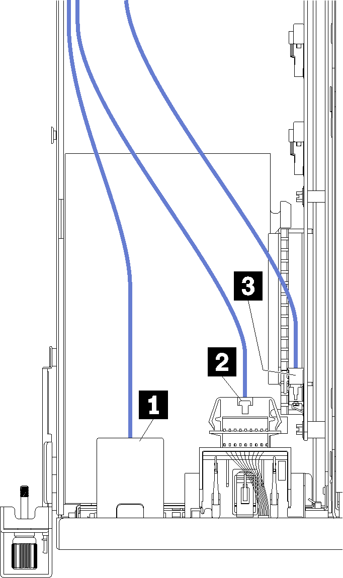
- Disconnect all cables (not shown):Figure 2. I/O cage cables
- Disconnect the PCIe adapter cables (all five of them) on the system board.Figure 3. I/O cage PCIe cable connectors
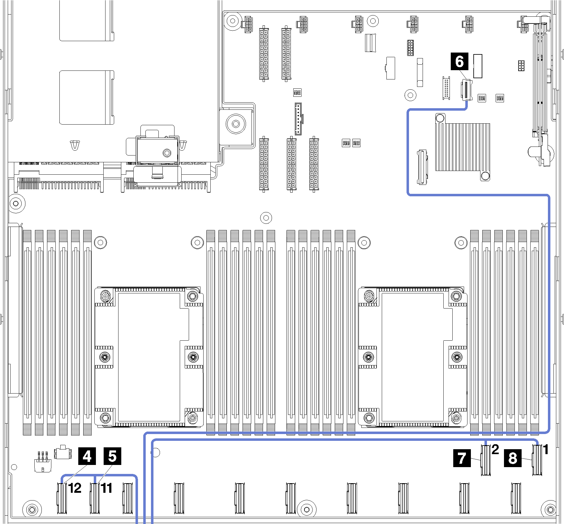
NoteIf you need to replace any of these cables, you will also need to remove the drive cage to access the cable connectors on the system board. SeeRemove the drive cage. - Disconnect the PCIe adapter cables (all five of them) on the system board.
Demo video