Kabelführung für PCIe-Switch-Platine
In diesem Abschnitt wird die Kabelführung für die PCIe-Switch-Platine beschrieben.
Wählen Sie je nach Position den entsprechenden Kabelführungsplan aus:
Im 2U-Compute-Shuttle
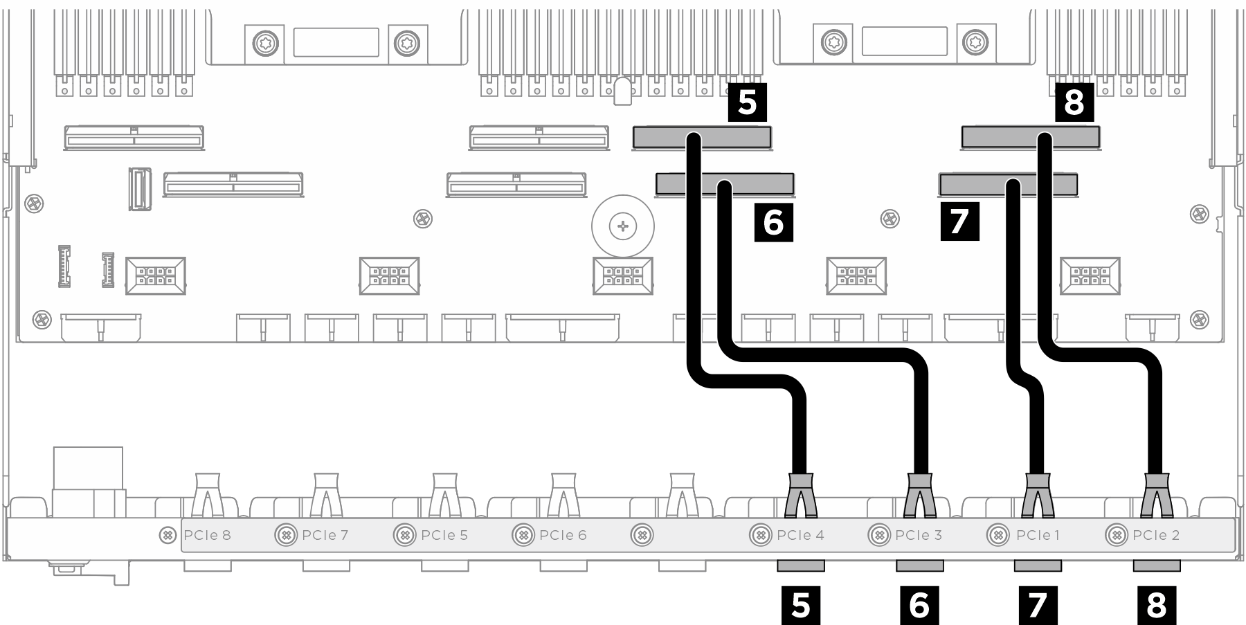
Signalkabel
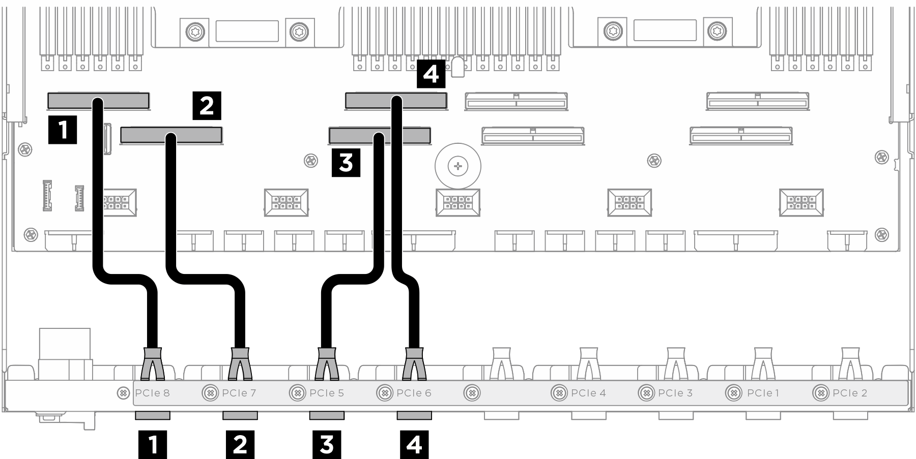
| Kabel | Vom | Zu |
|---|---|---|
| 1 | Hinterer Switch-Kabelbaum: PCIe 8-Kabel | Systemplatinenbaugruppe: PCIe-Anschluss 8 |
| 2 | Hinterer Switch-Kabelbaum: PCIe 7-Kabel | Systemplatinenbaugruppe: PCIe-Anschluss 7 |
| 3 | Hinterer Switch-Kabelbaum: PCIe-5-Kabel | Systemplatinenbaugruppe: PCIe-Anschluss 5 |
| 4 | Hinterer Switch-Kabelbaum: PCIe 6-Kabel | Systemplatinenbaugruppe: PCIe-Anschluss 6 |
| 5 | Hinterer Switch-Kabelbaum: PCIe 4-Kabel | Systemplatinenbaugruppe: PCIe-Anschluss 4 |
| 6 | Hinterer Switch-Kabelbaum: PCIe-3-Kabel | Systemplatinenbaugruppe: PCIe-Anschluss 3 |
| 7 | Hinterer Switch-Kabelbaum: PCIe 1-Kabel | Systemplatinenbaugruppe: PCIe-Anschluss 1 |
| 8 | Hinterer Switch-Kabelbaum: PCIe-2-Kabel | Systemplatinenbaugruppe: PCIe-Anschluss 2 |
GPU-Verwaltungskabel
Anmerkung
Führen Sie das Kabel wie beschrieben durch die Kabelführung.
Abbildung 1. Kabelführung für PCIe-Switch-Platine (GPU-Verwaltungskabel)
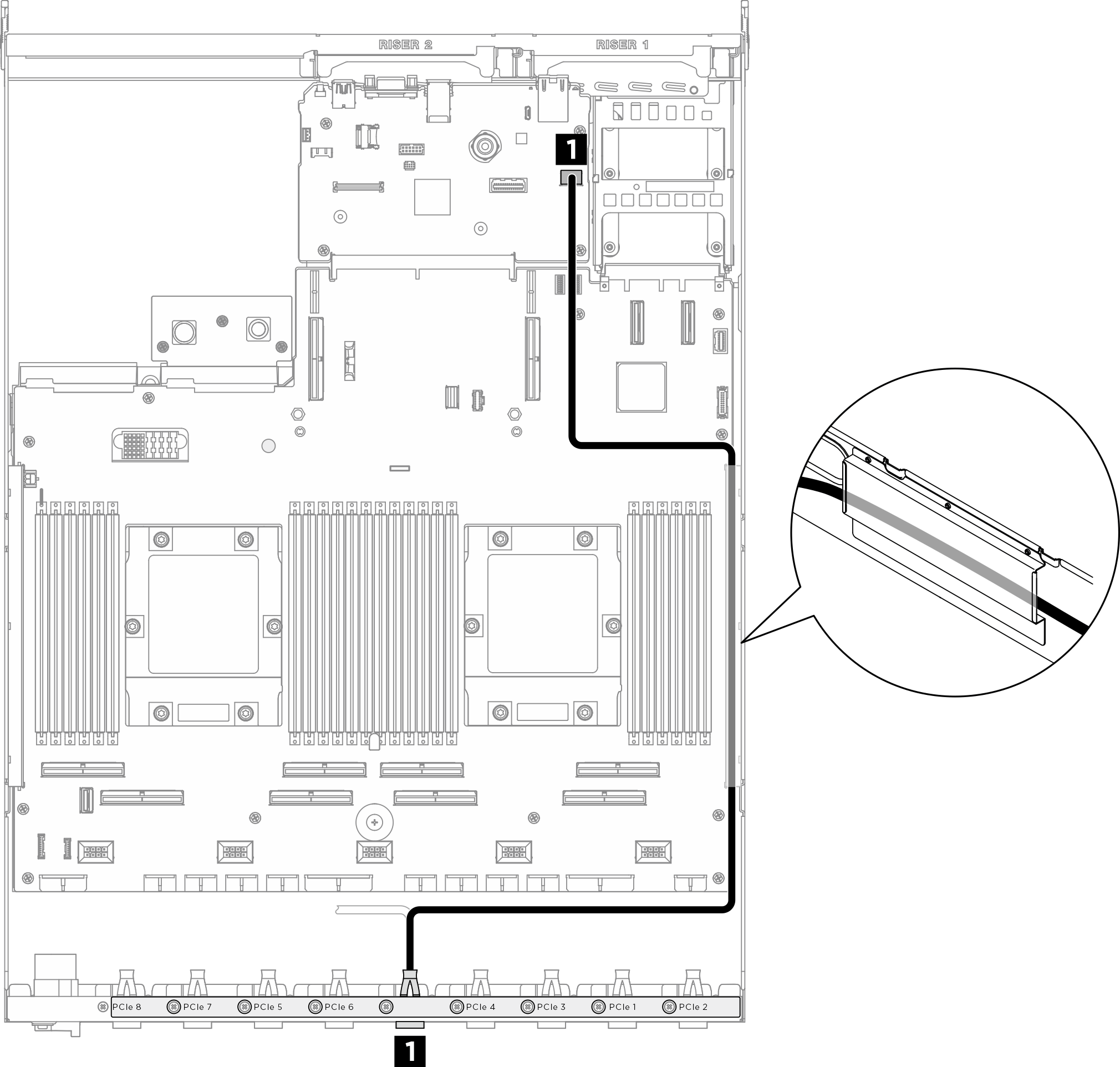
| Kabel | Vom | Zu |
|---|---|---|
| 1 | PCIe-Switch-Platine: GPU-Verwaltungskabel | Systemplatinenbaugruppe: PCIe SW MGMT-Anschluss |
Im 8U-GPU-Shuttle
Signalkabel
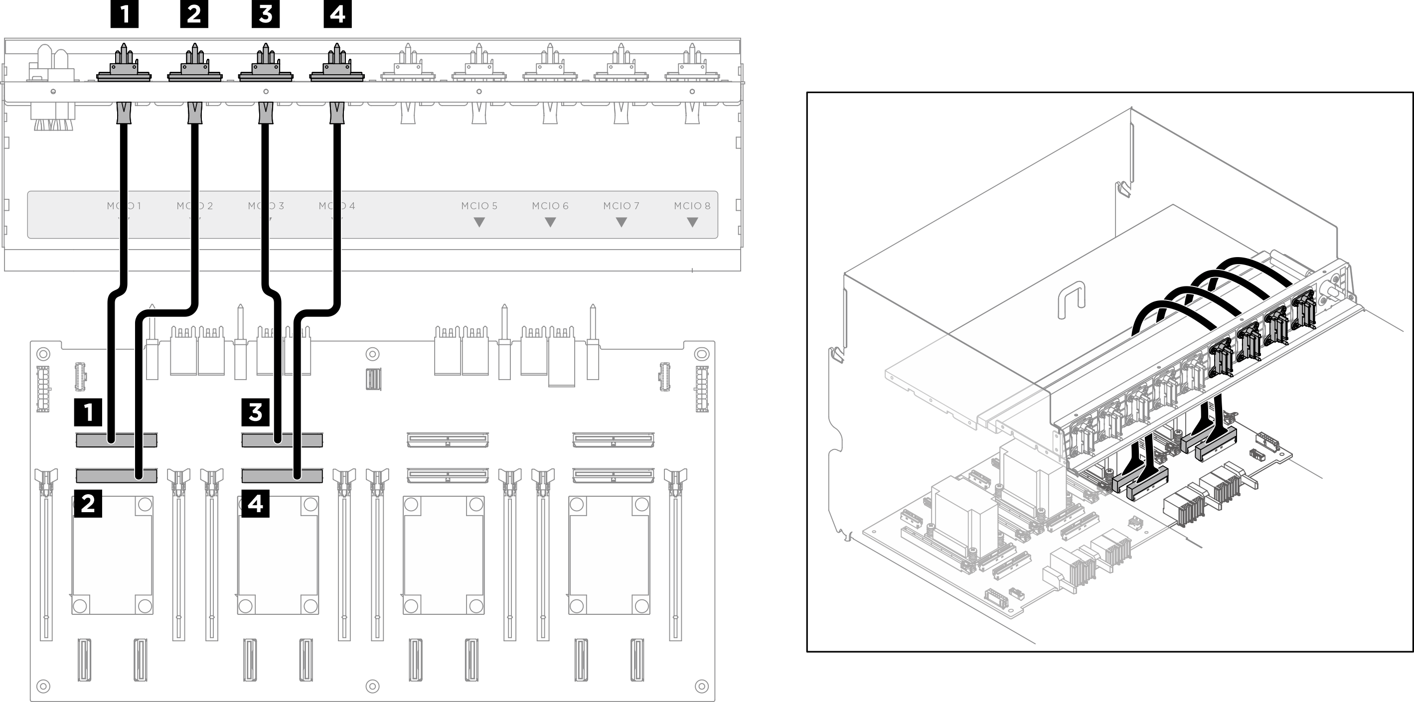
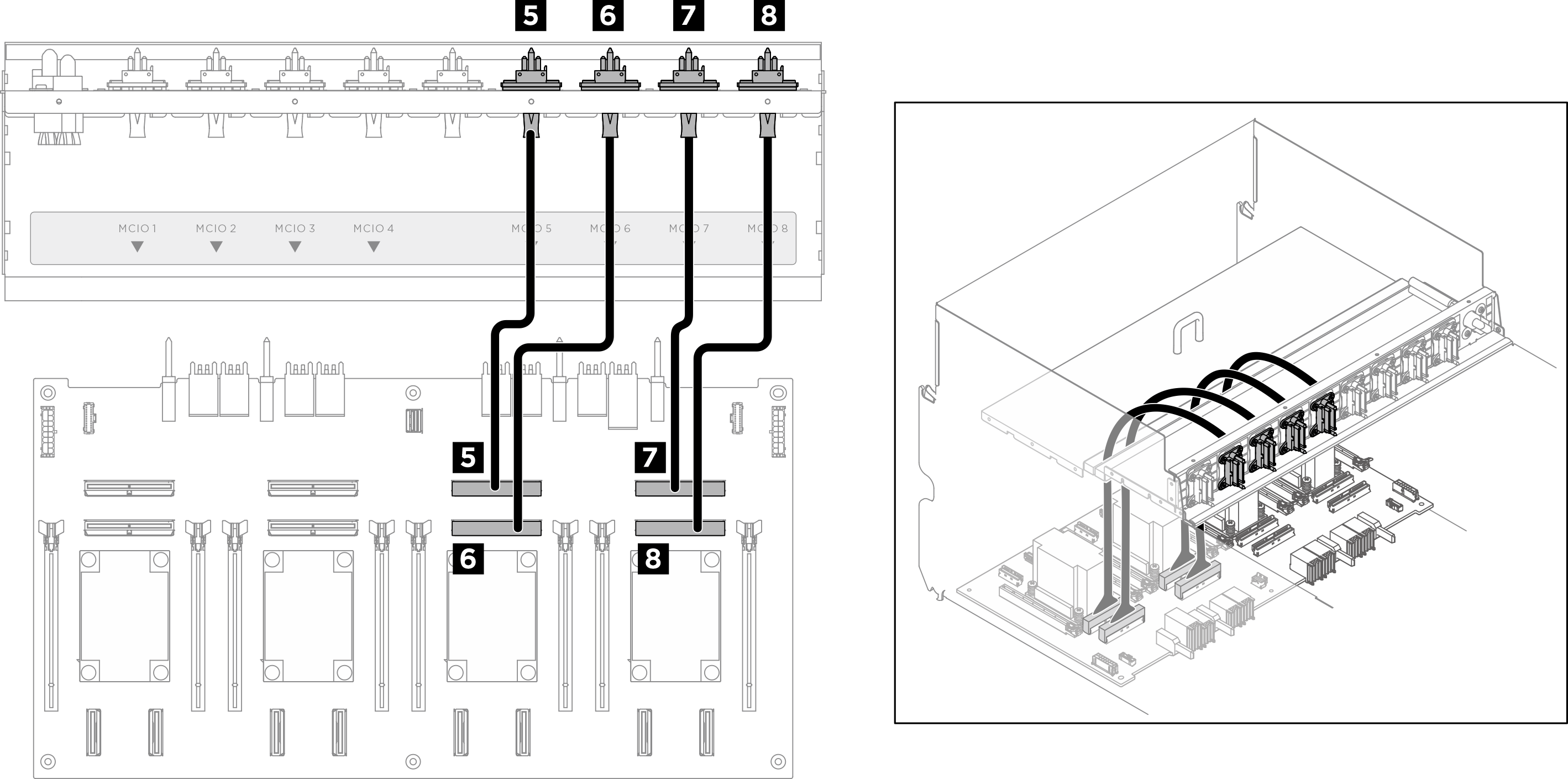
| Kabel | Vom | Zu | Etikett |
|---|---|---|---|
| 1 | Vorderen PCIe-Switch-Kabelbaum: MCIO 1-Kabel | PCIe-Switch-Platine: MCIO-Anschluss 1 (MCIO1) | MCIO 1 |
| 2 | Vorderen PCIe-Switch-Kabelbaum: MCIO 2-Kabel | PCIe-Switch-Platine: MCIO-Anschluss 2 (MCIO2) | MCIO 2 |
| 3 | Vorderen PCIe-Switch-Kabelbaum: MCIO 3-Kabel | PCIe-Switch-Platine: MCIO-Anschluss 3 (MCIO3) | MCIO 3 |
| 4 | Vorderen PCIe-Switch-Kabelbaum: MCIO 4-Kabel | PCIe-Switch-Platine: MCIO-Anschluss 4 (MCIO4) | MCIO 4 |
| 5 | Vorderen PCIe-Switch-Kabelbaum: MCIO 5-Kabel | PCIe-Switch-Platine: MCIO-Anschluss 5 (MCIO5) | MCIO 5 |
| 6 | Vorderen PCIe-Switch-Kabelbaum: MCIO 6-Kabel | PCIe-Switch-Platine: MCIO-Anschluss 6 (MCIO6) | MCIO 6 |
| 7 | Vorderen PCIe-Switch-Kabelbaum: MCIO 7-Kabel | PCIe-Switch-Platine: MCIO-Anschluss 7 (MCIO7) | MCIO 7 |
| 8 | Vorderen PCIe-Switch-Kabelbaum: MCIO 8-Kabel | PCIe-Switch-Platine: MCIO-Anschluss 8 (MCIO8) | MCIO 8 |
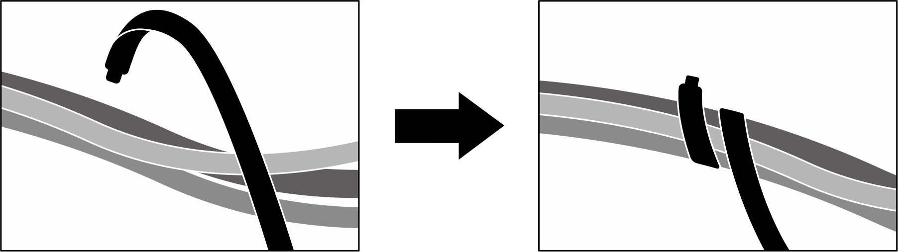
Nach dieser Aufgabe
Teilen Sie die Kabel, die an der PCIe-Switch-Platine angeschlossen sind, in vier Bündel auf, und befestigen Sie sie mit Kabelbindern.
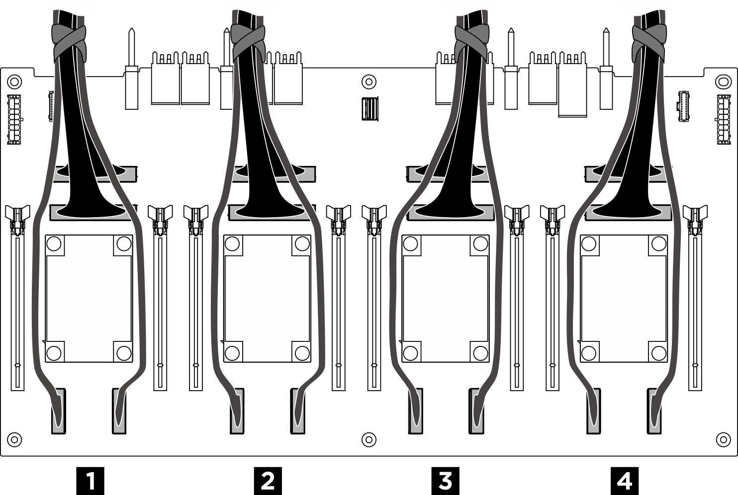
| Bündel | Kabel |
|---|---|
| 1 |
|
| 2 |
|
| 3 |
|
| 4 |
|
Abbildung 2. Sichern von Kabeln mit Kabelbindern
GPU-Verwaltungskabel
Abbildung 3. PCIe-Switch-Platine Kabelführung (GPU-Verwaltungskabel)
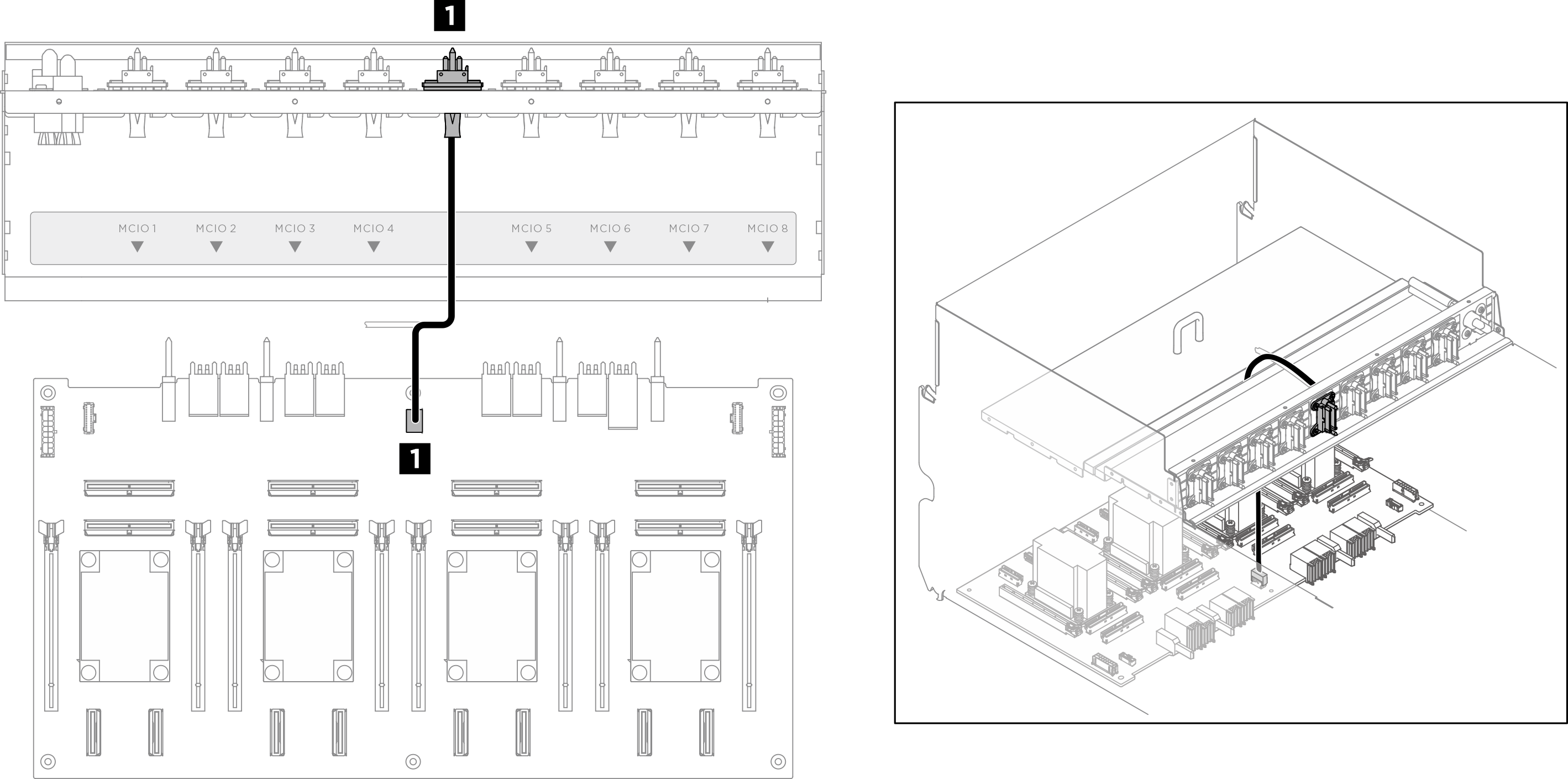
| Kabel | Vom | Zu |
|---|---|---|
| 1 | Vorderen PCIe-Switch-Kabelbaum: GPU-Verwaltungskabel | PCIe-Switch-Platine: GPU-Verwaltungsanschluss (MGMT) |
Netz‑ und Seitenbandkabel
Anmerkung
Führen Sie die Kabel gemäß den Anweisungen durch die Kabelklemmen.
Abbildung 4. Kabelführung für PCIe-Switch-Platine (Netz‑ und Seitenbandkabel)
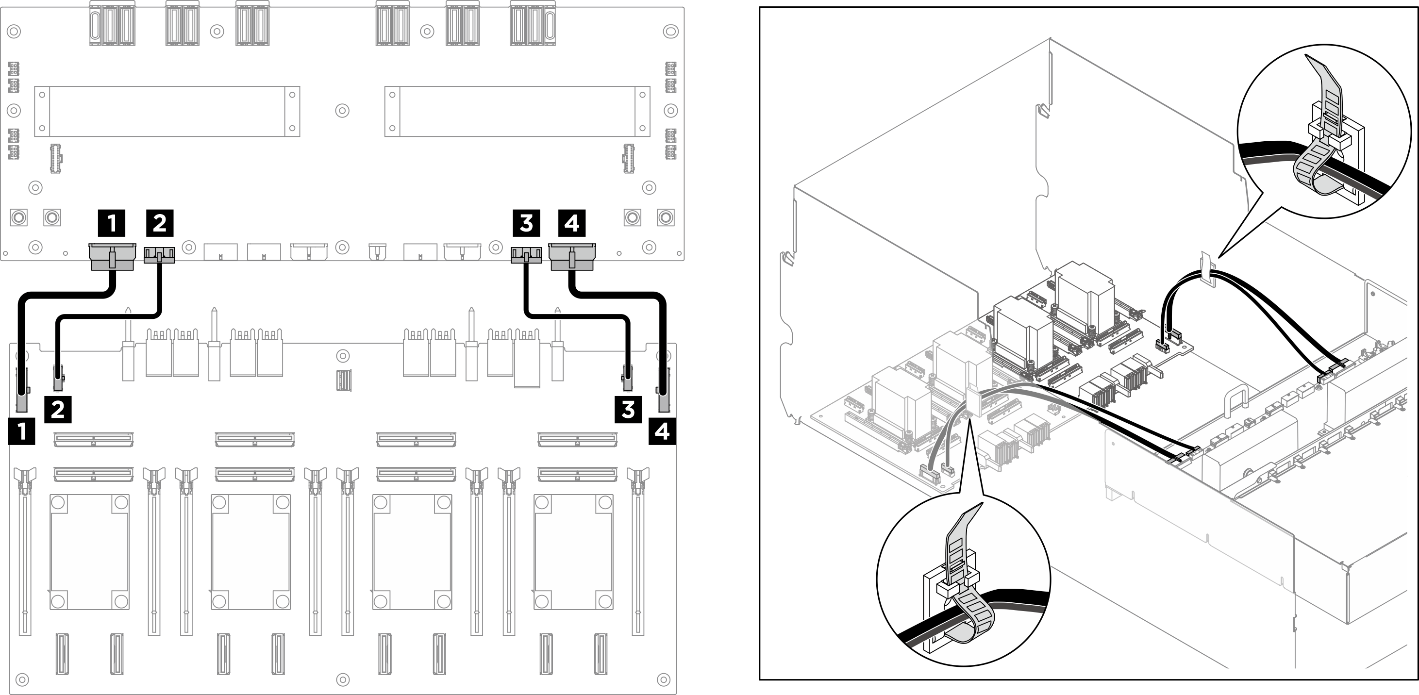
| Kabel | Vom | Zu |
|---|---|---|
| 1 | PCIe-Switch-Platine: Netzteilanschluss 1 der Stromversorgungsplatine (PDB PWR1) | Stromversorgungsplatine: Netzteilanschluss 1 der PCIe-Switch-Platine (FRONT RISER PWR1) |
| 2 | PCIe-Switch-Platine: Seitenbandanschluss 1 der Stromversorgungsplatine (PDB SB1) | Stromversorgungsplatine: Seitenbandanschluss 1 der PCIe-Switch-Platine (SWSB1) |
| 3 | PCIe-Switch-Platine: Netzteilanschluss 2 der Stromversorgungsplatine (PDB PWR2) | Stromversorgungsplatine: Netzteilanschluss 2 der PCIe-Switch-Platine (FRONT RISER PWR2) |
| 4 | PCIe-Switch-Platine: Seitenbandanschluss 2 der Stromversorgungsplatine (PDB SB2) | Stromversorgungsplatine: Seitenbandanschluss 2 der PCIe-Switch-Platine (SWSB2) |
Feedback geben