PCIe switch board cable routing
Use the section to understand the cable routing for the PCIe switch board.
Based on the location, select the corresponding routing plan:
In 2U compute shuttle
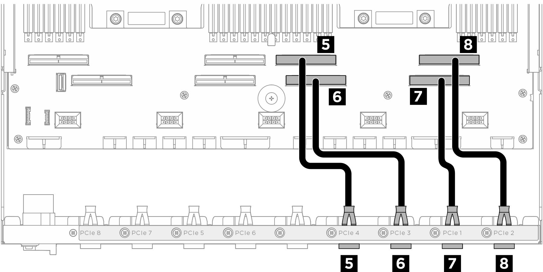
Signal cables
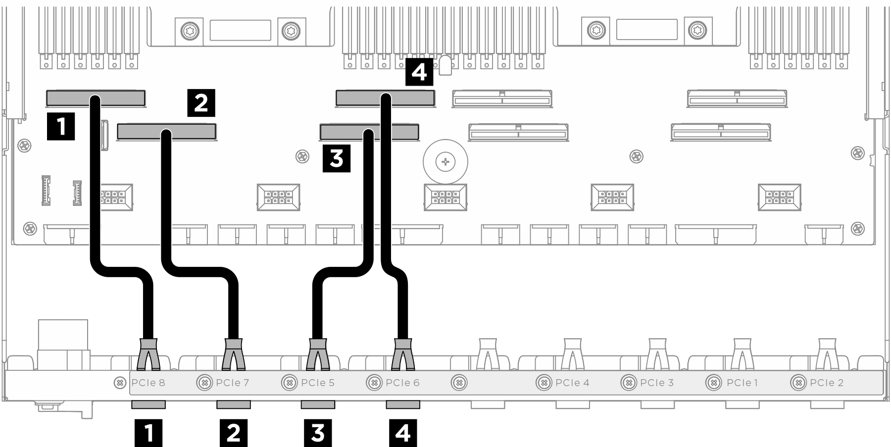
| Cable | From | To |
|---|---|---|
| 1 | Rear switch cable harness: PCIe 8 cable | System board assembly: PCIe connector 8 |
| 2 | Rear switch cable harness: PCIe 7 cable | System board assembly: PCIe connector 7 |
| 3 | Rear switch cable harness: PCIe 5 cable | System board assembly: PCIe connector 5 |
| 4 | Rear switch cable harness: PCIe 6 cable | System board assembly: PCIe connector 6 |
| 5 | Rear switch cable harness: PCIe 4 cable | System board assembly: PCIe connector 4 |
| 6 | Rear switch cable harness: PCIe 3 cable | System board assembly: PCIe connector 3 |
| 7 | Rear switch cable harness: PCIe 1 cable | System board assembly: PCIe connector 1 |
| 8 | Rear switch cable harness: PCIe 2 cable | System board assembly: PCIe connector 2 |
GPU management cable
Note
Make sure to route the cable through the cable guide as instructed.
Figure 1. PCIe switch board cable routing (GPU management cable)
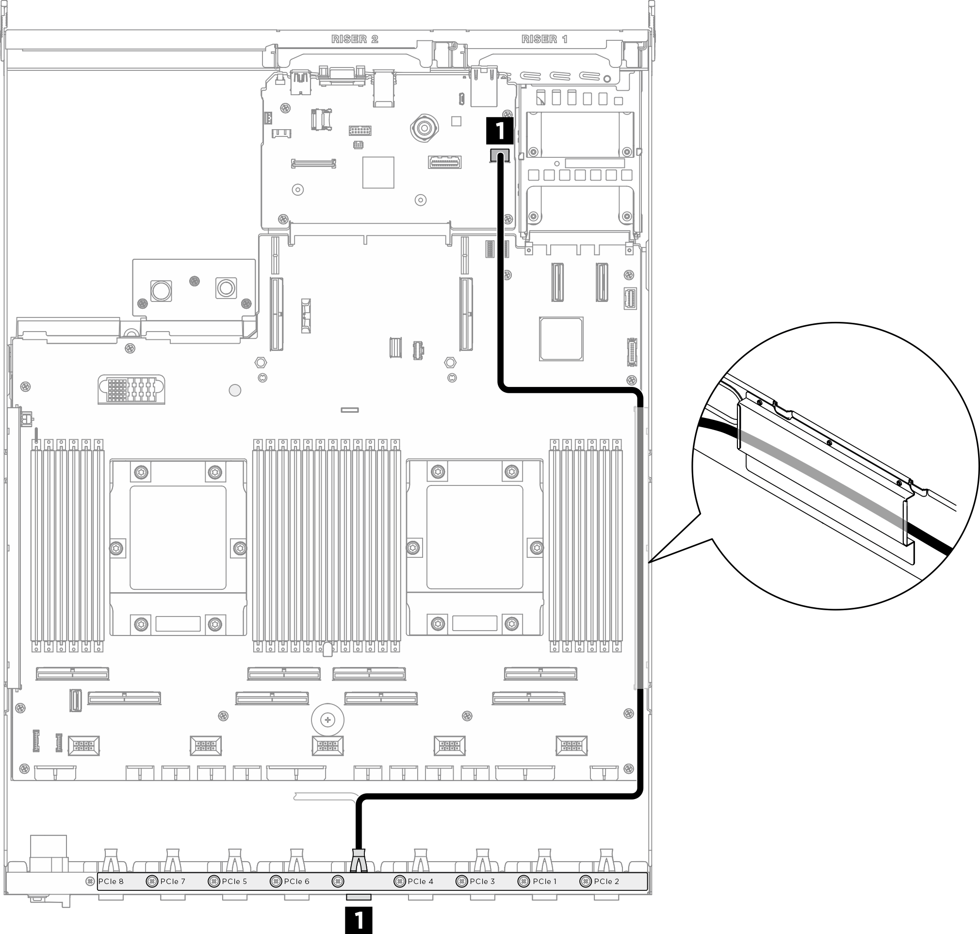
| Cable | From | To |
|---|---|---|
| 1 | PCIe switch board: GPU management cable | System board assembly: PCIe SW MGMT connector |
In 8U GPU shuttle
Signal cables
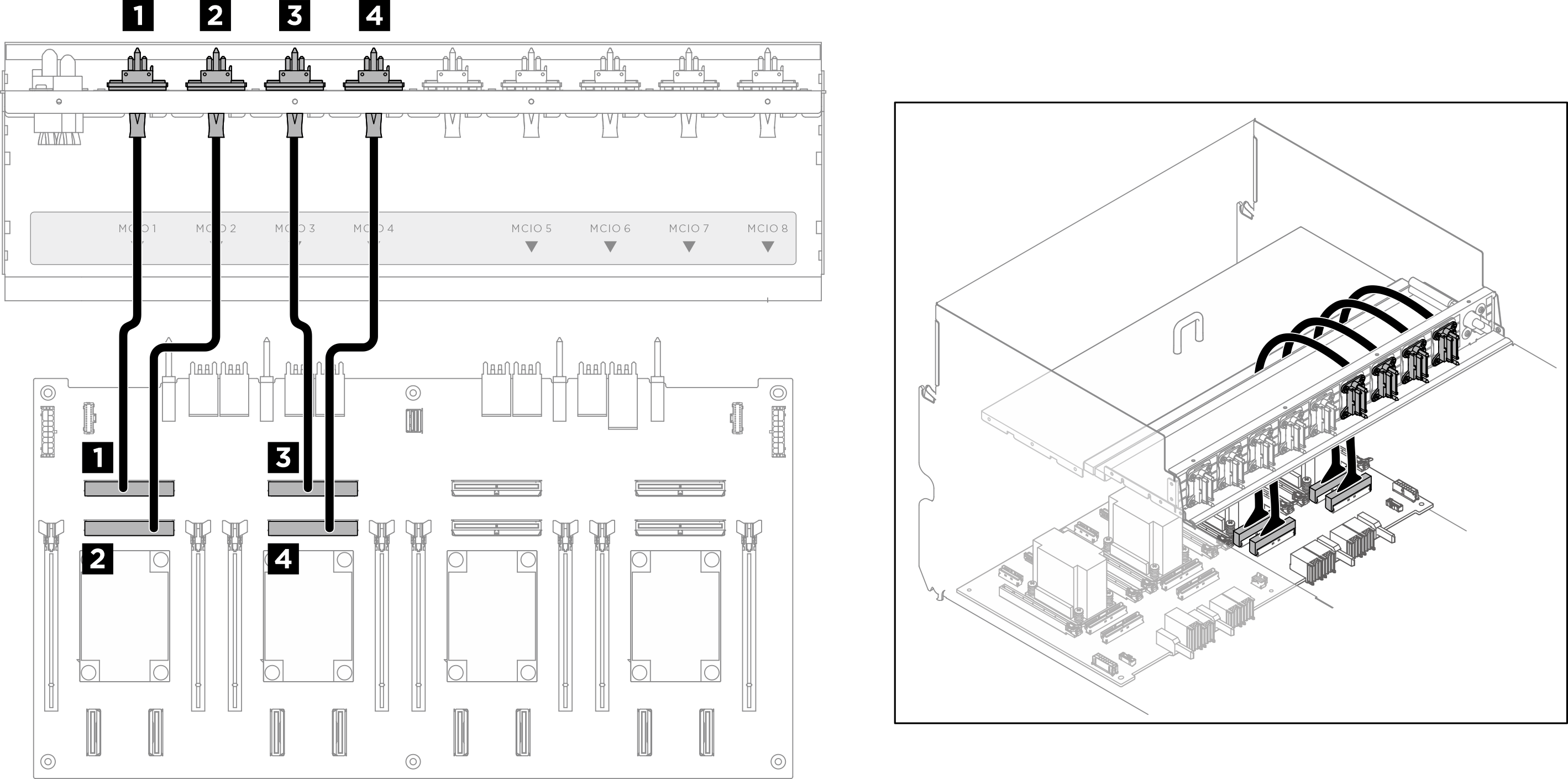
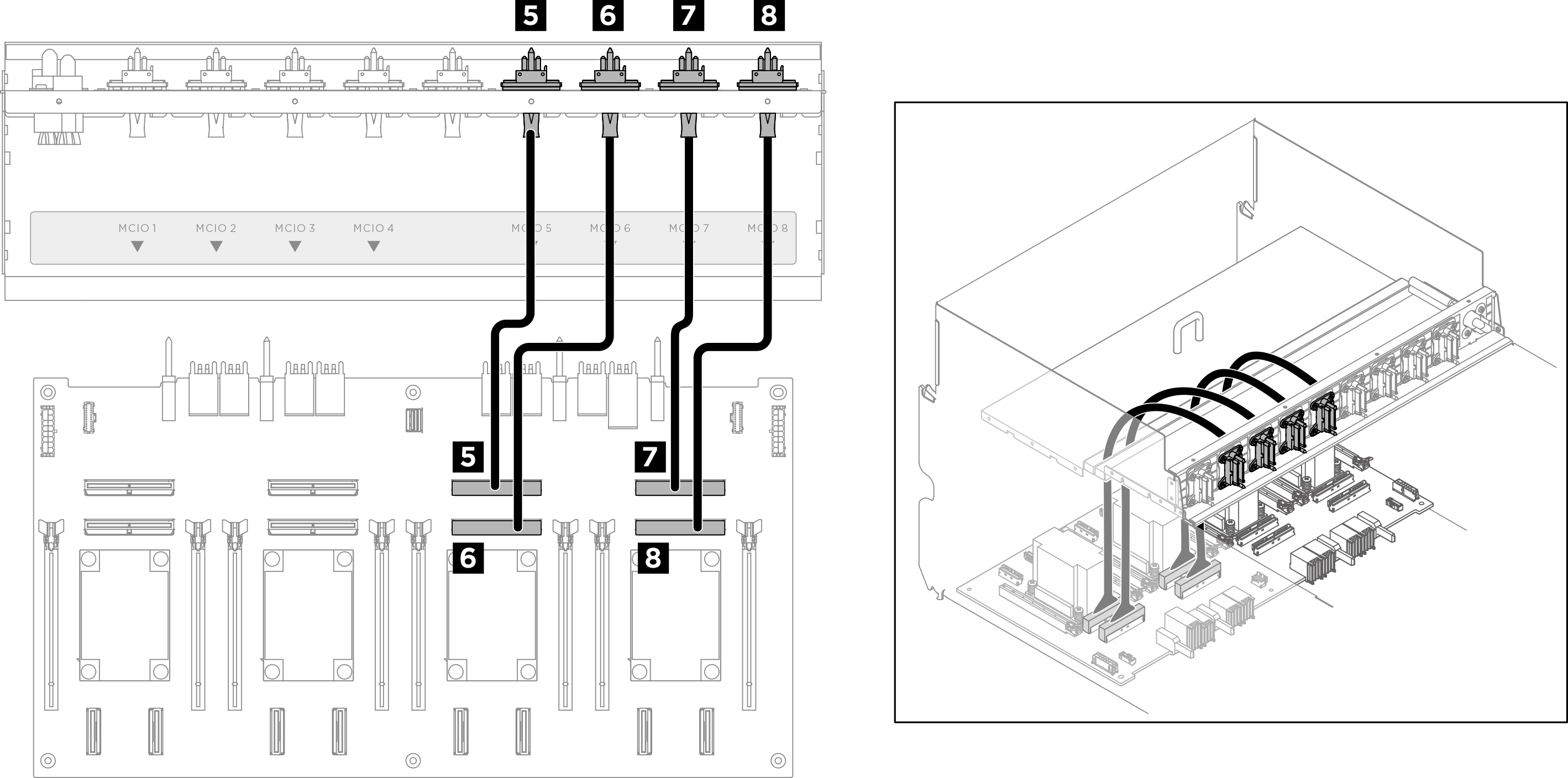
| Cable | From | To | Label |
|---|---|---|---|
| 1 | Front PCIe switch cable harness: MCIO 1 cable | PCIe switch board: MCIO connector 1 (MCIO1) | MCIO 1 |
| 2 | Front PCIe switch cable harness: MCIO 2 cable | PCIe switch board: MCIO connector 2 (MCIO2) | MCIO 2 |
| 3 | Front PCIe switch cable harness: MCIO 3 cable | PCIe switch board: MCIO connector 3 (MCIO3) | MCIO 3 |
| 4 | Front PCIe switch cable harness: MCIO 4 cable | PCIe switch board: MCIO connector 4 (MCIO4) | MCIO 4 |
| 5 | Front PCIe switch cable harness: MCIO 5 cable | PCIe switch board: MCIO connector 5 (MCIO5) | MCIO 5 |
| 6 | Front PCIe switch cable harness: MCIO 6 cable | PCIe switch board: MCIO connector 6 (MCIO6) | MCIO 6 |
| 7 | Front PCIe switch cable harness: MCIO 7 cable | PCIe switch board: MCIO connector 7 (MCIO7) | MCIO 7 |
| 8 | Front PCIe switch cable harness: MCIO 8 cable | PCIe switch board: MCIO connector 8 (MCIO8) | MCIO 8 |
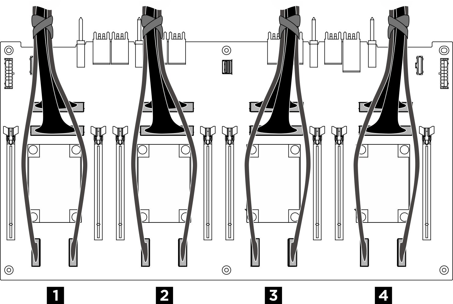
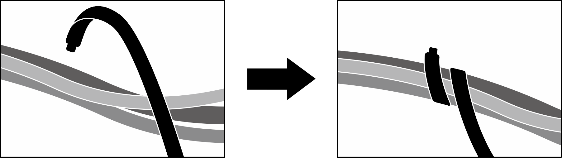
After you finish
Divide the cables connected to the PCIe switch board into four bundles, and secure them with cable ties.
| Bundle | Cable |
|---|---|
| 1 |
|
| 2 |
|
| 3 |
|
| 4 |
|
Figure 2. Securing cables with cable ties
GPU management cable
Figure 3. PCIe switch board cable routing (GPU management cable)
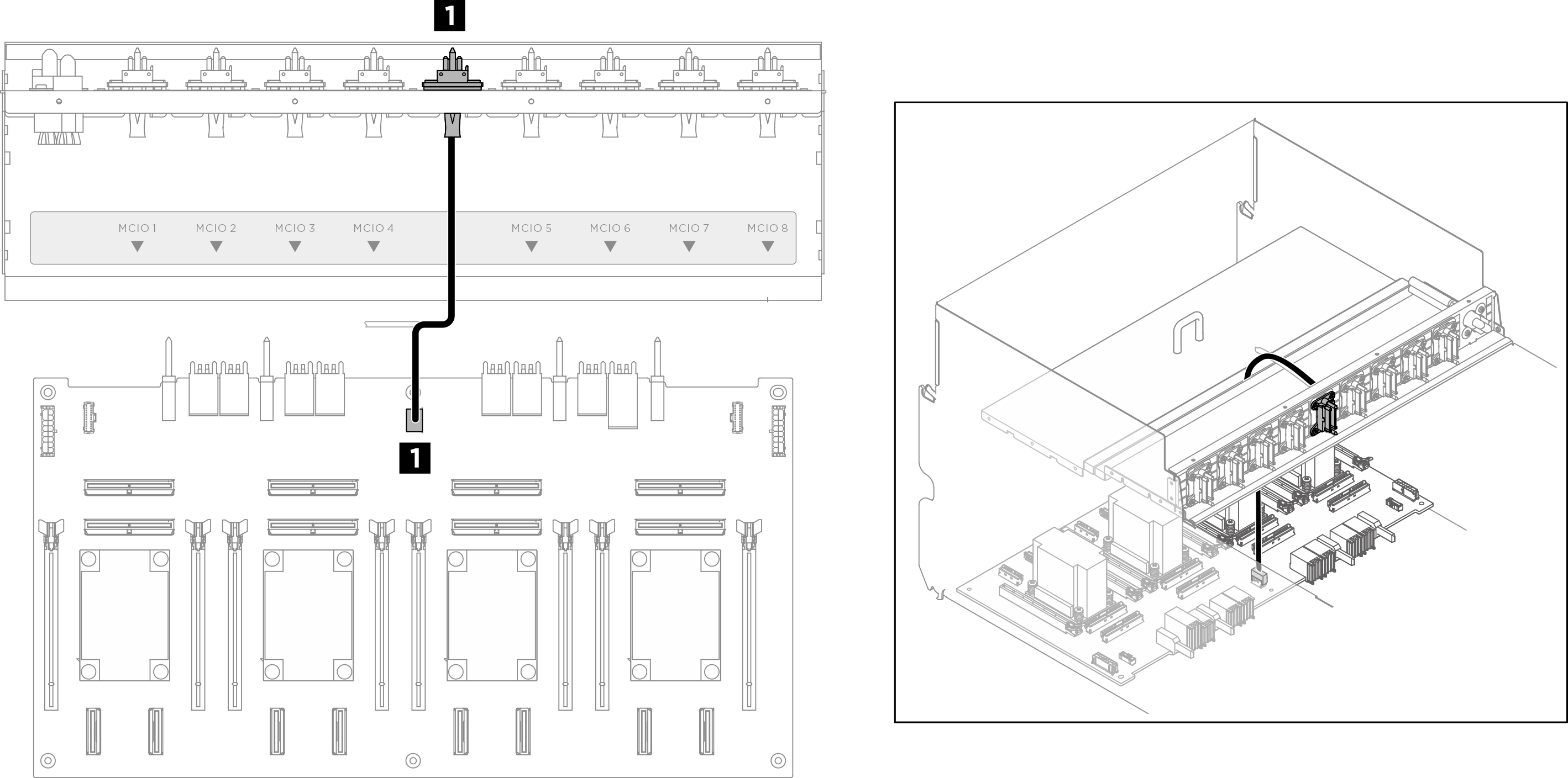
| Cable | From | To |
|---|---|---|
| 1 | Front PCIe switch cable harness: GPU management cable | PCIe switch board: GPU management connector (MGMT) |
Power and sideband cables
Note
Make sure to route the cables through the cable clips as instructed.
Figure 4. PCIe switch board cable routing (power and sideband cables)
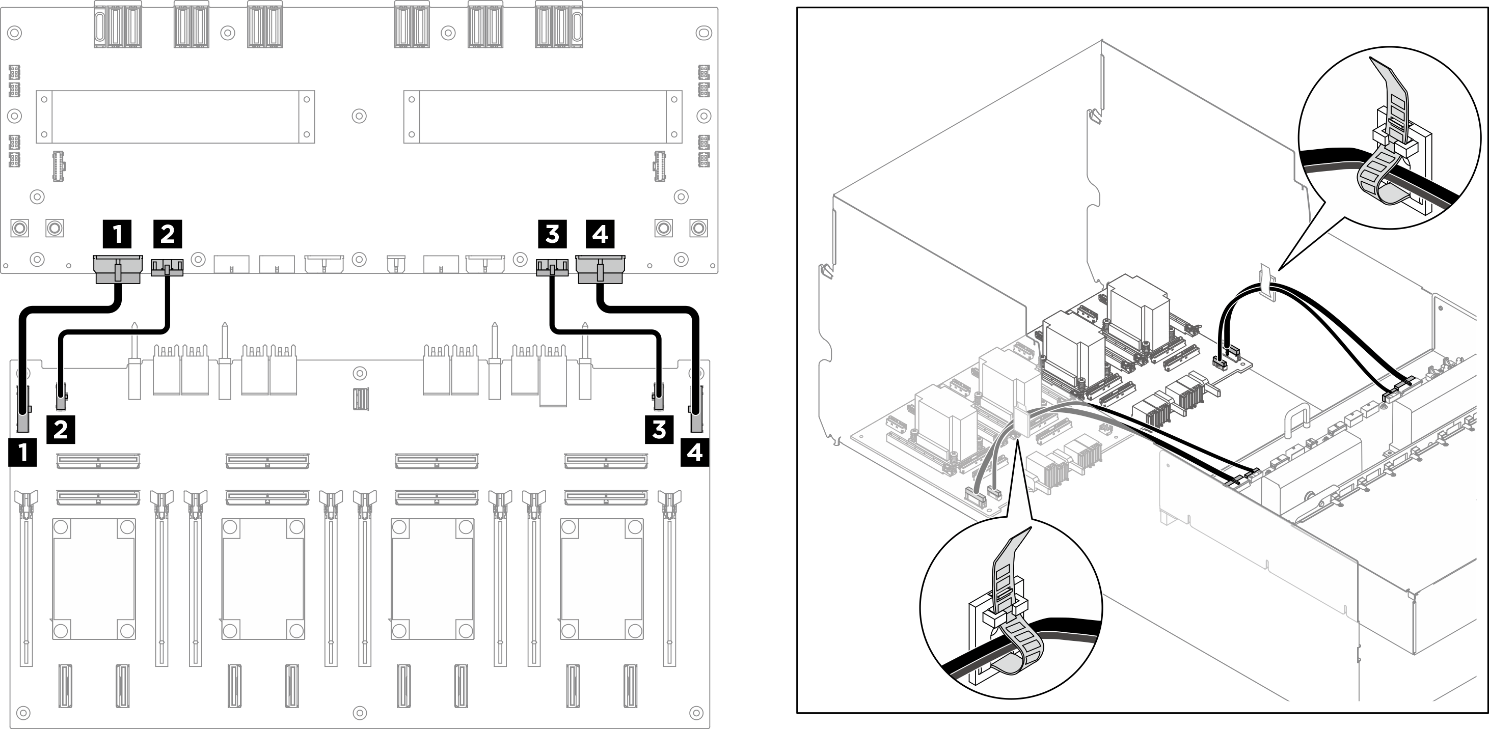
| Cable | From | To |
|---|---|---|
| 1 | PCIe switch board: Power distribution board power connector 1 (PDB PWR1) | Power distribution board: PCIe switch board power connector 1 (FRONT RISER PWR1) |
| 2 | PCIe switch board: Power distribution board sideband connector 1 (PDB SB1) | Power distribution board: PCIe switch board sideband connector 1 (SWSB1) |
| 3 | PCIe switch board: Power distribution board sideband connector 2 (PDB SB2) | Power distribution board: PCIe switch board sideband connector 2 (SWSB2) |
| 4 | PCIe switch board: Power distribution board power connector 2 (PDB PWR2) | Power distribution board: PCIe switch board power connector 2 (FRONT RISER PWR2) |
Give documentation feedback