Front I/O module and integrated diagnostics panel cable routing
Use the section to understand the cable routing for the front I/O module and the integrated diagnostics panel.
Based on the location, select the corresponding routing plan:
In 2U compute shuttle
Note
Make sure to route the cables through the cable guide as instructed.
Figure 1. Front I/O module and integrated diagnostics panel cable routing
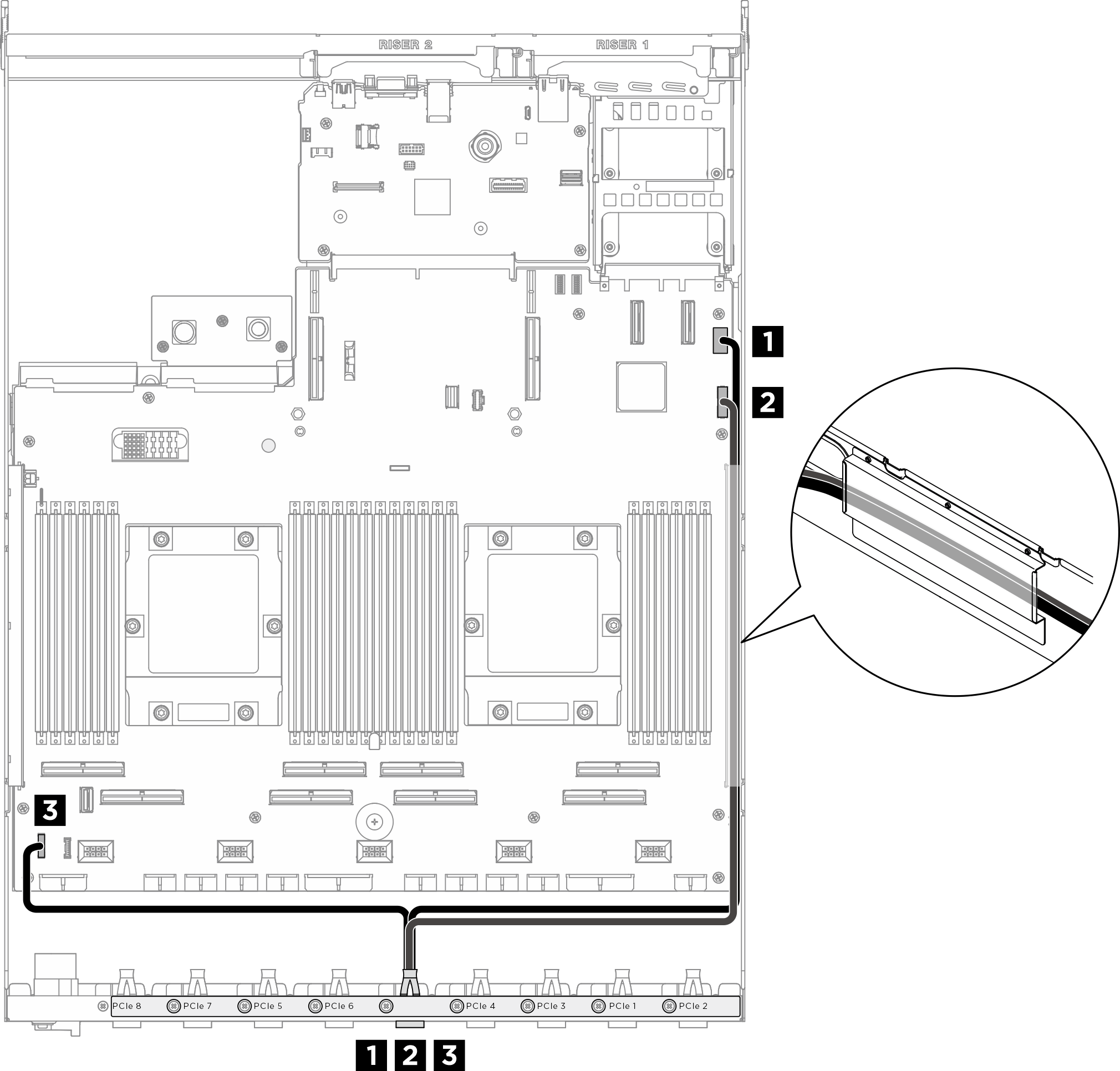
| Cable | From | To |
|---|---|---|
| 1 | Rear PCIe switch cable harness: VGA cable | System board assembly: Front VGA connector |
| 2 | Rear PCIe switch cable harness: USB cable | System board assembly: Front USB connector |
| 3 | Rear PCIe switch cable harness: Integrated diagnostics panel cable | System board assembly: Integrated diagnostics panel connector |
For GPU management cable routing on the system board assembly, see PCIe switch board cable routing.
In 8U GPU shuttle
Figure 2. Front I/O module and integrated diagnostics panel cable routing
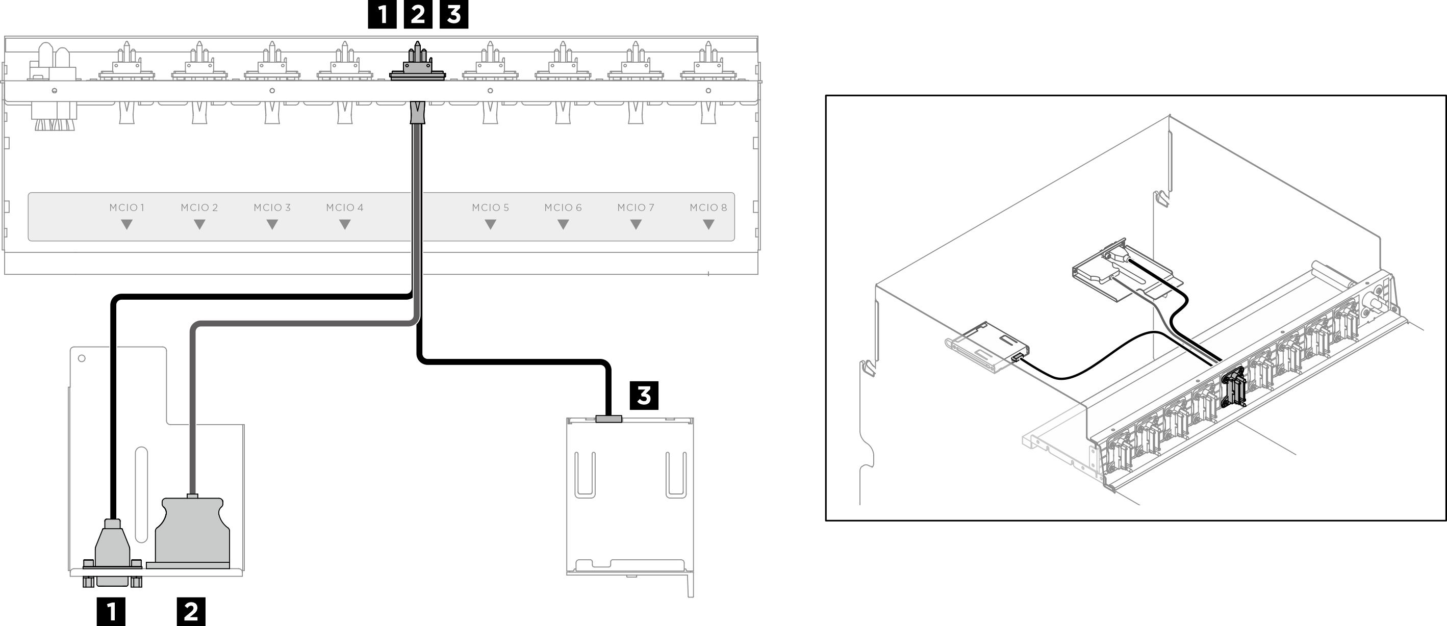
| Cable | From | To |
|---|---|---|
| 1 | Front PCIe switch cable harness: VGA cable | Front I/O module |
| 2 | Front PCIe switch cable harness: USB cable | Front I/O module |
| 3 | Front PCIe switch cable harness: Integrated diagnostics panel cable | Integrated diagnostics panel |
For GPU management cable routing on the PCIe switch board, see PCIe switch board cable routing.
Give documentation feedback