2.5-inch drive backplane cable routing
Use the section to understand the cable routing for the 2.5-inch drive backplane.
Based on the location of the drive backplane, select the corresponding routing plan:
Backplane 1
Figure 1. Backplane 1 cable routing
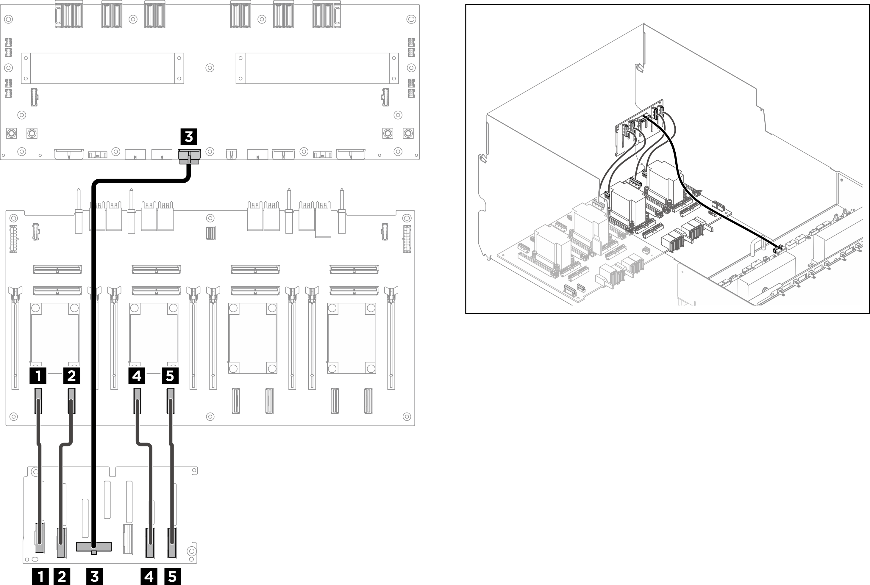
| Cable | From | To | Label |
|---|---|---|---|
| 1 | Backplane 1: NVMe connector 0-1 | PCIe switch board: NVMe connector 1 (NVME1) |
|
| 2 | Backplane 1: NVMe connector 2-3 | PCIe switch board: NVMe connector 2 (NVME2) |
|
| 3 | Backplane 1: Power connector | Power distribution board: Backplane 1 power connector (BP1 PWR) | N/A |
| 4 | Backplane 1: NVMe connector 4-5 | PCIe switch board: NVMe connector 3 (NVME3) |
|
| 5 | Backplane 1: NVMe connector 6-7 | PCIe switch board: NVMe connector 4 (NVME4) |
|
Backplane 2
Figure 2. Backplane 2 cable routing
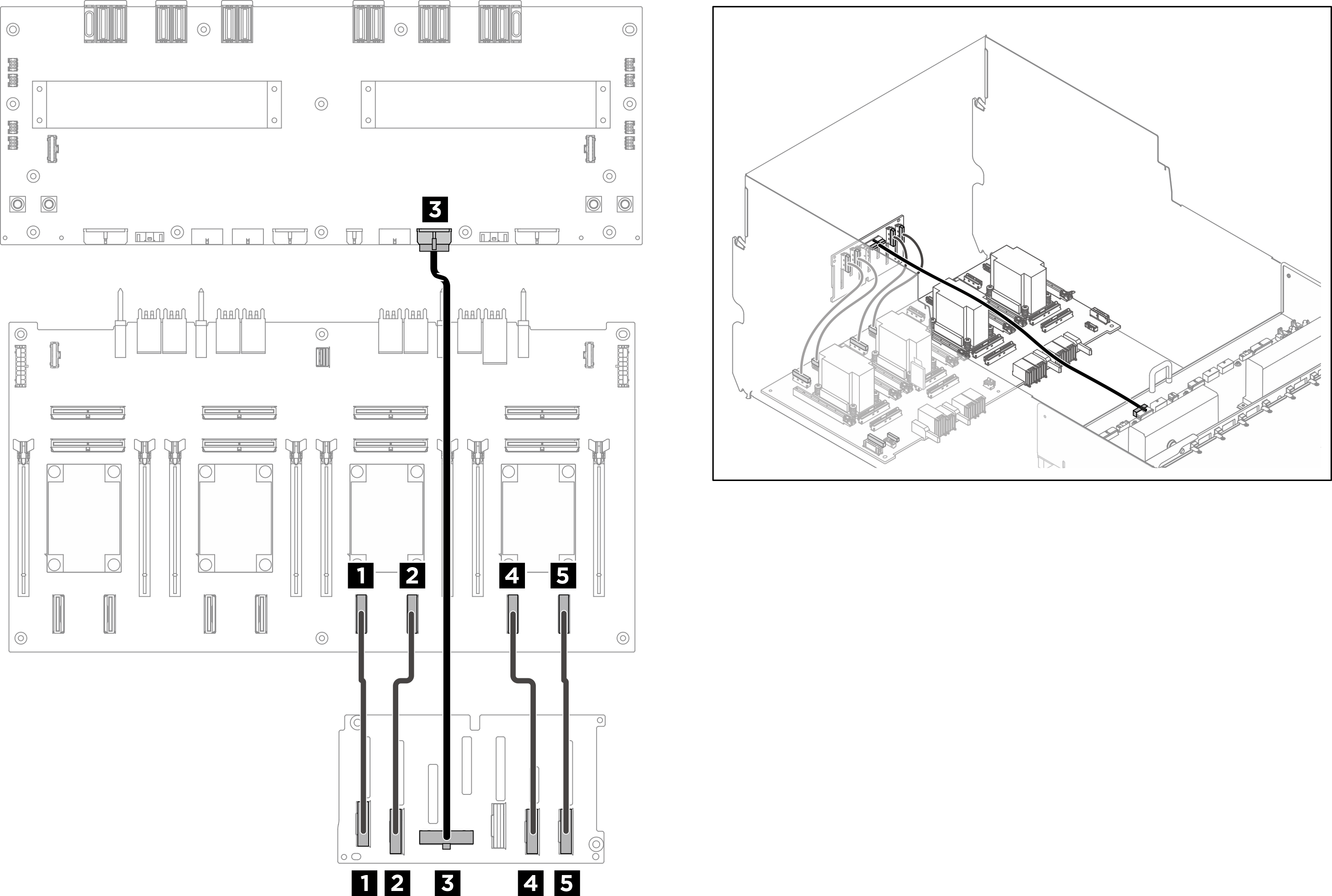
| Cable | From | To | Label |
|---|---|---|---|
| 1 | Backplane 2: NVMe connector 0-1 | PCIe switch board: NVMe connector 5 (NVME5) |
|
| 2 | Backplane 2: NVMe connector 2-3 | PCIe switch board: NVMe connector 6 (NVME6) |
|
| 3 | Backplane 2: Power connector | Power distribution board: Backplane 2 power connector (BP2 PWR) | N/A |
| 4 | Backplane 2: NVMe connector 4-5 | PCIe switch board: NVMe connector 7 (NVME7) |
|
| 5 | Backplane 2: NVMe connector 6-7 | PCIe switch board: NVMe connector 8 (NVME8) |
|
After you finish
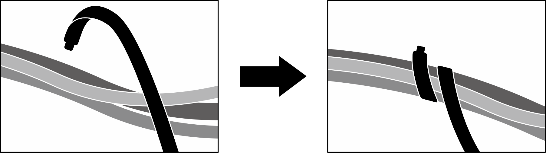
Divide the cables connected to the PCIe switch board into four bundles, and secure them with cable ties.
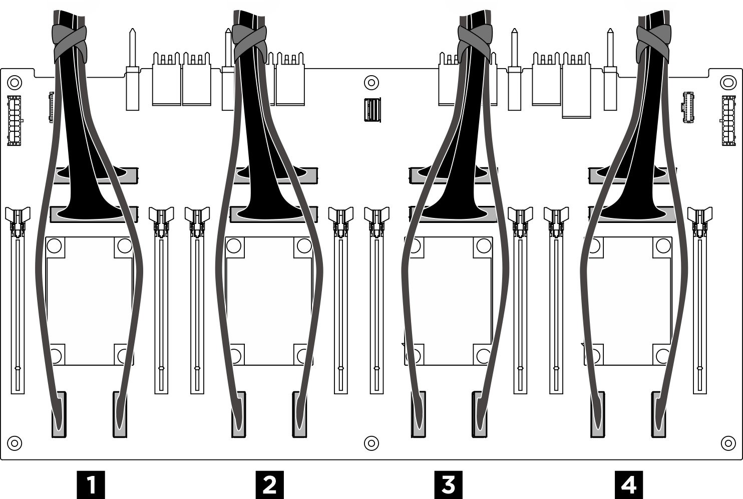
| Bundle | Cable |
|---|---|
| 1 |
|
| 2 |
|
| 3 |
|
| 4 |
|
Figure 3. Securing cables with cable ties
Give documentation feedback