System-board-assembly connectors for cable routing
The following illustrations show the internal connectors on the system board assembly that are used for internal cable routing.
Figure 1. System-board-assembly connectors for cable routing
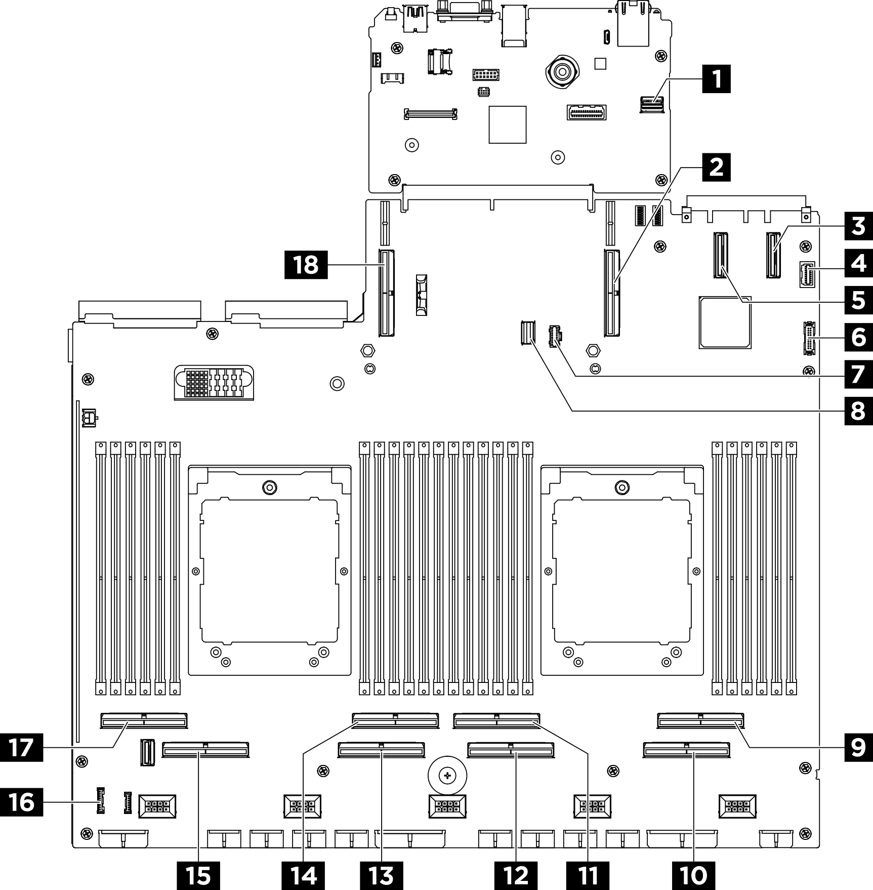
| 1 PCIe SW MGMT connector | 2 PCIe connector 9 |
| 3 PCIe connector 11 | 4 Front VGA connector |
| 5 PCIe connector 12 | 6 Front USB connector |
| 7 M.2 power connector | 8 M.2 signal connector |
| 9 PCIe connector 2 | 10 PCIe connector 1 |
| 11 PCIe connector 4 | 12 PCIe connector 3 |
| 13 PCIe connector 5 | 14 PCIe connector 6 |
| 15 PCIe connector 7 | 16 Integrated diagnostics panel connector |
| 17 PCIe connector 8 | 18 PCIe connector 10 |
Give documentation feedback