Rear view
This section contains information on the rear view.
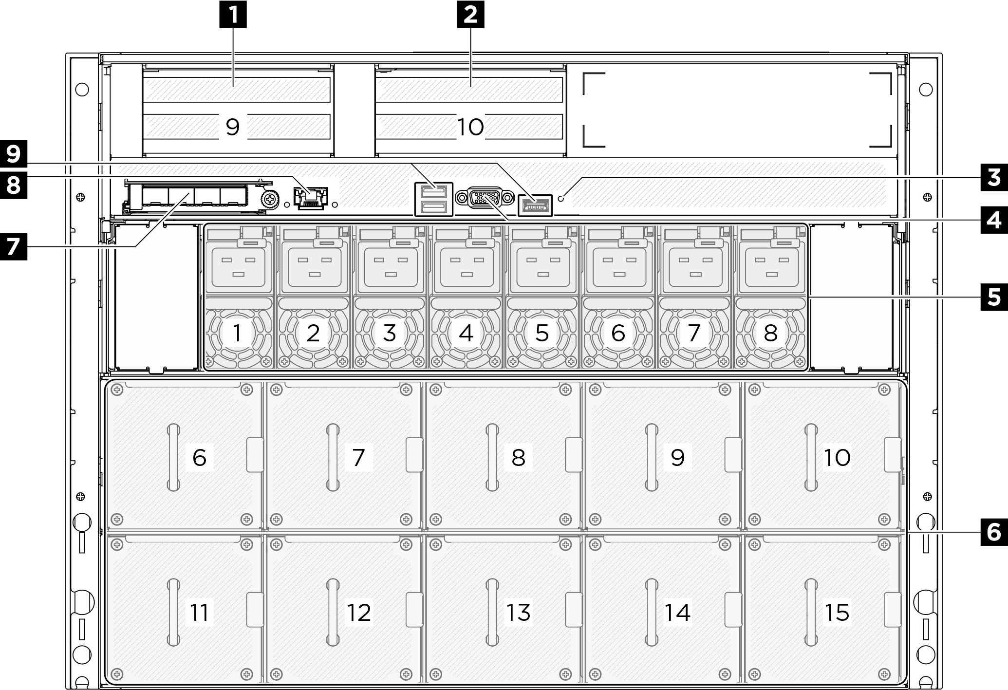
| 1 PCIe riser 1 (PCIe slot 9) | 2 PCIe riser 2 (PCIe slot 10) |
| 3 NMI button | 4 VGA connector |
| 5 Power supply units | 6 Rear fans |
| 7 OCP module | 8 XCC system management port (10/100/1000 Mbps RJ-45) |
| 9 USB 3.1 Gen 1 (5 Gbps) connectors (total of three connectors) |
1/2 PCIe riser 1/2
Install PCIe adapters into these risers. See the following table for PCIe slots corresponding to the risers.
| PCIe riser | PCIe slot |
|---|---|
| 1 PCIe riser 1 | Slot 9: PCIe Gen5 x16, FH/HL |
| 2 PCIe riser 2 | Slot 10: PCIe Gen5 x16, FH/HL |
4 VGA connector
Connect a monitor to this connector.
5 Power supply units
Install power supply units to these bays, connect them to power cords. Make sure the power cords are connected properly. Following are the power supplies supported by this system:
- 2600-watt Titanium, input power 200-240 Vac
For more information on the power supply LEDs, see Power supply LEDs.
6 Rear fans
Install rear fans in this space. See Install a hot-swap fan (front and rear) for more information.
7 OCP 3.0 module
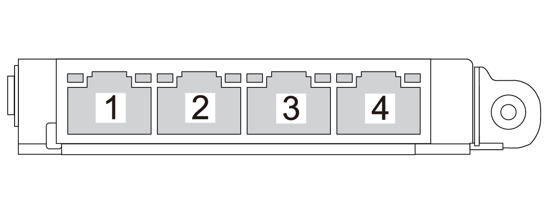
8 XCC system management port (10/100/1000 Mbps RJ-45)
The server has a 10/100/1000 Mbps RJ-45 connector dedicated to Lenovo XClarity Controller (XCC) functions. Through the system management port, you can access the Lenovo XClarity Controller directly by connecting your laptop to the management port using an Ethernet cable. Make sure that you modify the IP settings on the laptop so that it is on the same network as the server default settings. A dedicated management network provides additional security by physically separating the management network traffic from the production network.
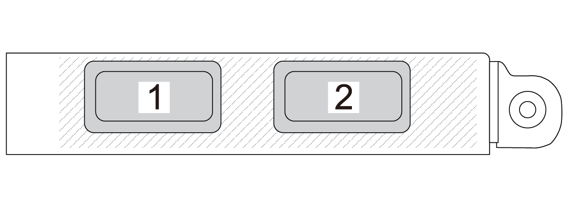
9 USB 3.1 Gen 1 (5 Gbps) connectors
There are three USB 3.1 Gen 1 (5 Gbps) connectors on the rear of the server. Connect a USB device, such as a mouse, keyboard, or other devices, to either of these connectors.