Front view
This section contains information on the front view.
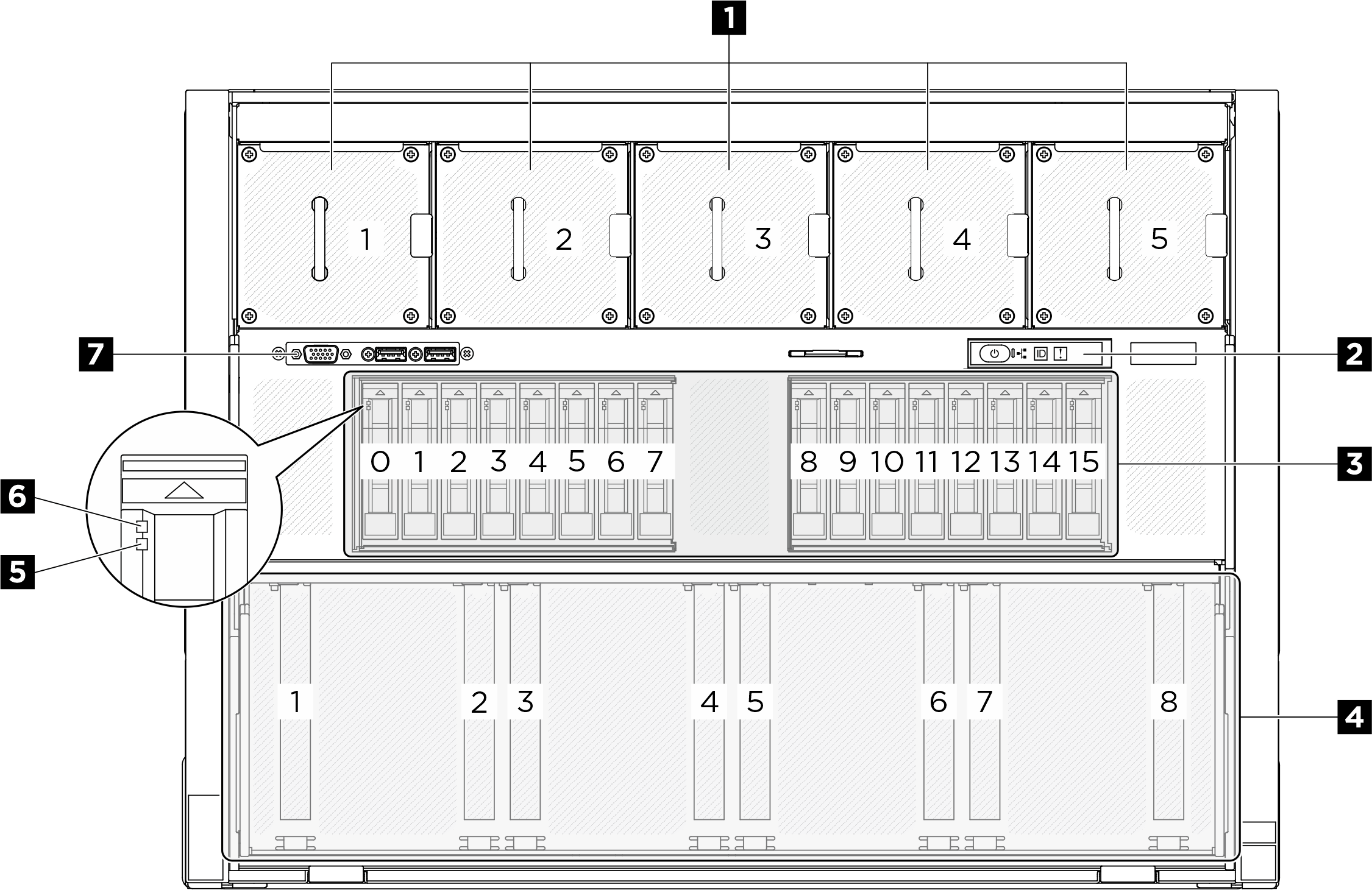
| 1 Front fans | 2 Integrated diagnostics panel |
| 3 2.5-inch drive bays (bay 0 to 15) | 4 PCIe switch shuttle (PCIe slot 1-8) |
| 5 Drive status LED (yellow) | 6 Drive activity LED (green) |
| 7 Front I/O module |
1 Front fans
Install front fans in this space. See Install a hot-swap fan (front and rear) for more information.
2 Integrated diagnostics panel
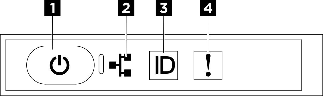
| 1 Power button with power status LED (green) | 2 Network activity LED (green) |
| 3 System ID button with system ID LED (blue) | 4 System Error LED (yellow) |
1 Power button with power status LED (green)
You can press the power button to power on the server when you finish setting up the server. You also can hold the power button for several seconds to power off the server if you cannot shut down the server from the operating system. The states of the power LED are as follows:
| Status | Color | Description |
|---|---|---|
| Off | None | No power supply is properly installed, or the LED itself has failed. |
| Flashing rapidly (four times per second) | Green | The server is turned off and is not ready to be turned on. The power button is disabled. This will last approximately 5 to 10 seconds. |
| Flashing slowly (once per second) | Green | The server is turned off and is ready to be turned on. You can press the power button to turn on the server. |
| Lit | Green | The server is turned on. |
2 Network activity LED (green)
The network activity LED helps you identify the network connectivity and activity.
| Status | Color | Description |
|---|---|---|
| On | Green | The server is connected to a network. |
| Blinking | Green | The network is connected and active. |
| Off | None | The server is disconnected from the network. |
3 System ID button with system ID LED (blue)
Use this system ID button and the blue system ID LED to visually locate the server. Each time you press the system ID button, the state of the system ID LED changes. The LED can be changed to on, blinking, or off. You can also use the Lenovo XClarity Controller or a remote management program to change the state of the system ID LED to assist in visually locating the server among other servers.
4 System Error LED (yellow)
The system error LED helps you to determine if there are any system errors.
| Status | Color | Description | Action |
|---|---|---|---|
| On | Yellow | An error has been detected on the server. Causes might include one or more of the following errors:
| Check the LCD display or the event log to determine the exact cause of the error. |
| Off | None | The server is off or the server is on and is working correctly. | None. |
For more information about the integrated diagnostics panel, see Integrated diagnostics panel.
3 2.5-inch drive bays (bay 0 to 15)
Install 2.5-inch NVMe drives to these bays. See Install a 2.5-inch hot-swap drive for more information.
4 PCIe switch shuttle (PCIe slot 1-8)
- PCIe Gen5 x16, FH/HL
5 Drive status LED (yellow)
- The LED is lit: the drive has failed.
- The LED is flashing slowly (once per second): the drive is being rebuilt.
- The LED is flashing rapidly (three times per second): the drive is being identified.
6 Drive activity LED (green)
Each hot-swap drive comes with an activity LED. When this LED is flashing, it indicates that the drive is in use.
7 Front I/O module
For more information about the front I/O module, see Front I/O module.