Cable routing for 2.5-inch drives
Follow the instructions in this section to learn how to do cable routing for 2.5-inch drives.
Go through the following list to acquire necessary information before starting cable routing for 2.5-inch drives.
Preliminary parts removal and installation
- Make sure the following components are removed beforehand:
- Top cover (see Remove the top cover)
- Processor and memory expansion tray (see Remove the processor and memory expansion tray)
- Fan cage (see Remove the fan cage assembly)
Make sure to install all the drive backplanes that you plan to installed (see Install a drive backplane).
Power cables
Connect power cables to drive backplanes as illustrated.
Figure 1. Drive backplane power cables
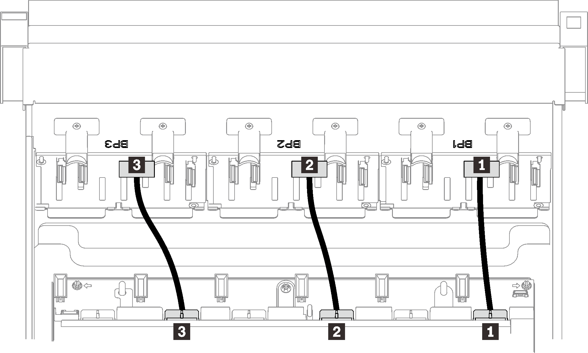
| 1 Drive backplane 1 to connector 1 | 3 Drive backplane 3 to connector 3 |
| 2 Drive backplane 2 to connector 2 |
Cable guides
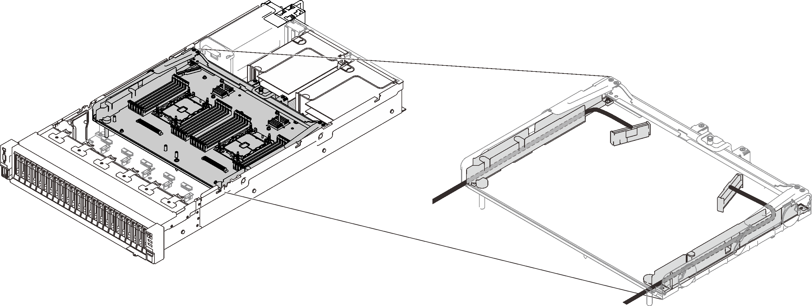
Make sure all the signal cables go through the cable guides on the system board and the memory expansion tray.
Figure 2. Cable guides on the system board
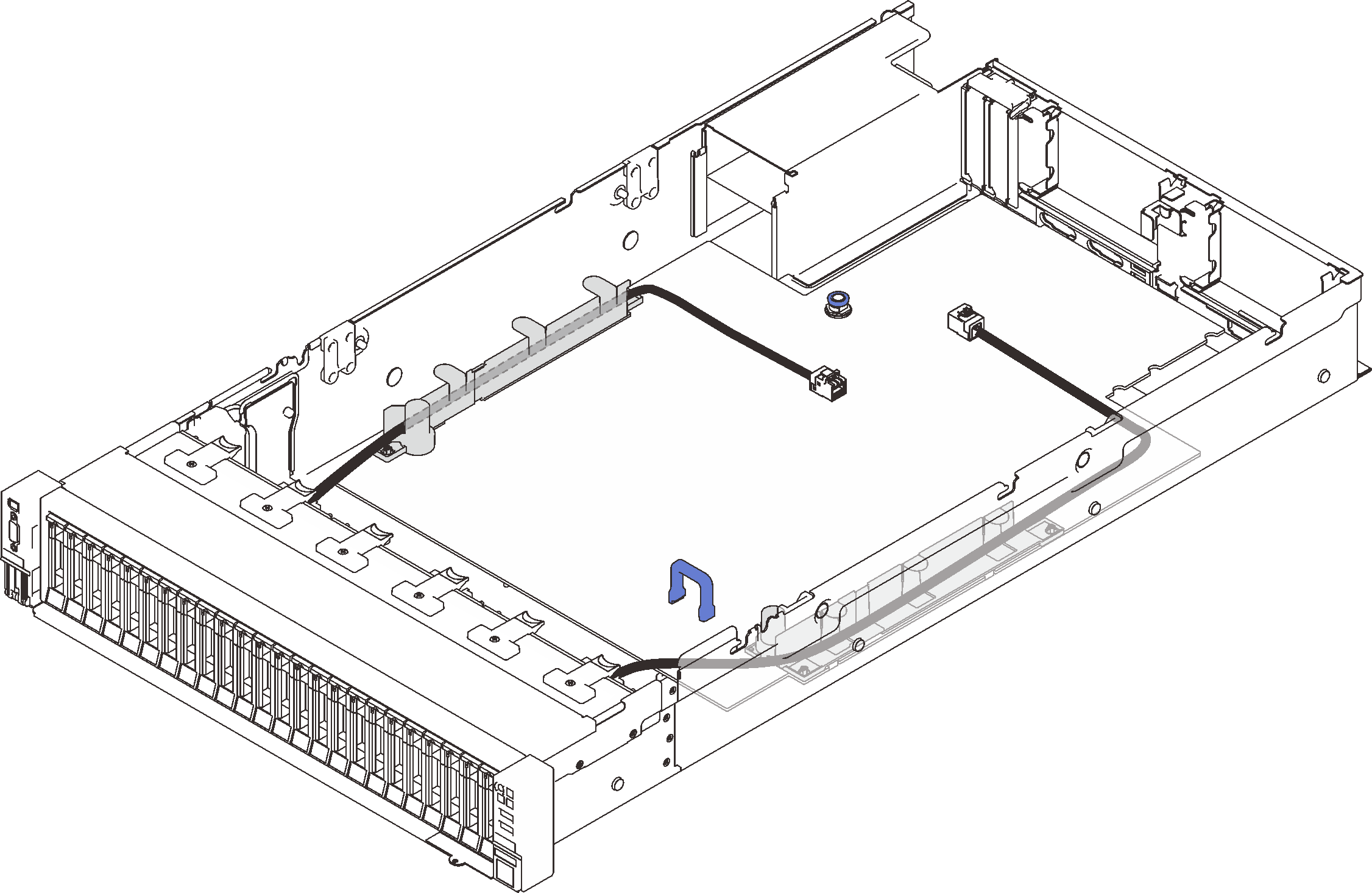
Figure 3. Cable guides on the processor and memory expansion tray
SAS/SATA cables for Gen3 and Gen4 RAID adapters
When picking cables for 8i and 16i RAID adapters from SAS/SATA cable kits, make sure to choose the cables based on the generation of RAID adapters that you plan to install:
- Gen3 RAID adapters (430-8i, 930-8i, 430-16i, 530-16i, 930-16i): MiniSAS to Slimline cable
- Gen4 RAID adapters (940-8i, 940-16i): Slimline cable
Backplane and PCIe slot reference
See the label on the cable for reference of PCIe slots to installed RAID adapters or PCIe switch cards in. For example, “BP 1/4” and “Slot 1/8 means the cable could be applied to the following scenarios:
- Connecting backplane 1 to RAID adapter that is installed in slot 1
- Connecting backplane 4 to RAID adapter that is installed in slot 8
Give documentation feedback