Connecting cables to the NVMe switch cards
Follow the instructions in this section to learn how to connect cables to the NVMe switch cards.
When working on cable routing plans that involve NVMe switch cards, perform the procedure in the following order.
- Connect the four PCIe cables to the two NVMe switch cards.Figure 1. Connecting cables to the NVMe switch cards
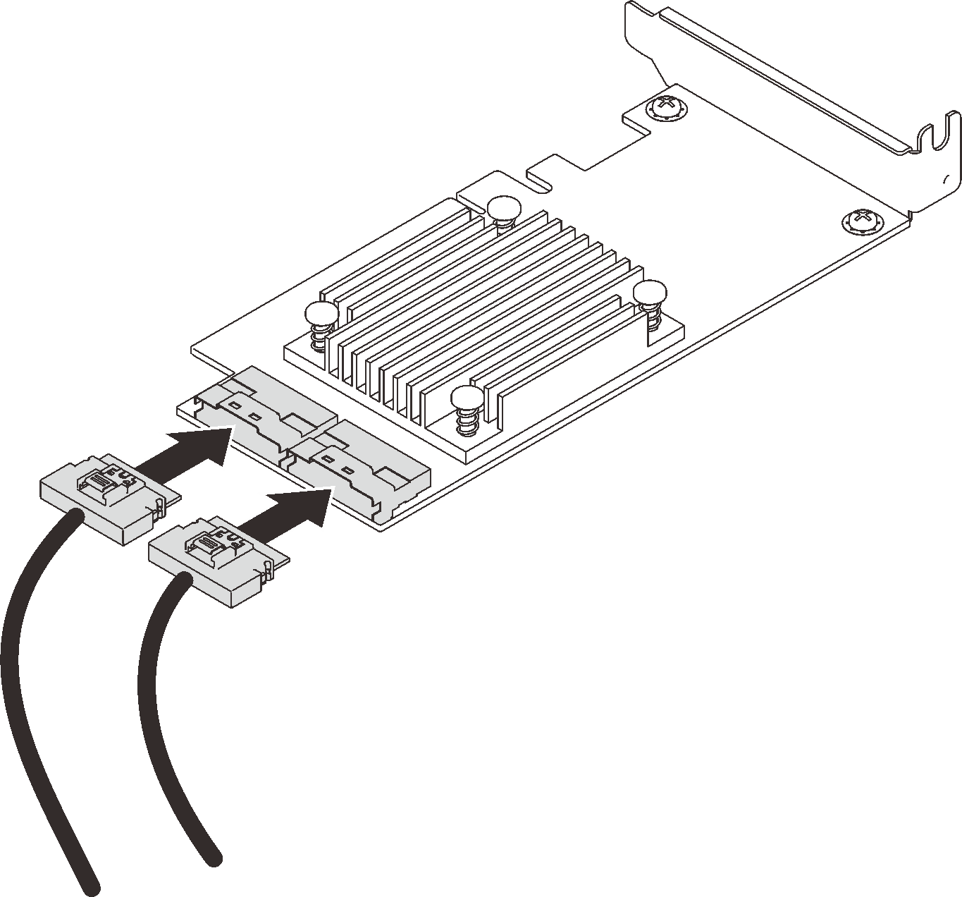 NoteMake sure to match the drive backplane and NVMe switch card connectors as following:
Table 1. Drive backplane and NVMe switch card connectors AnyBay/NVMe drive backplane connector Switch card connector 0-1 C0 2-3 C1 4-5 C0 6-7 C1
Give documentation feedback