NVMe backplane combinations
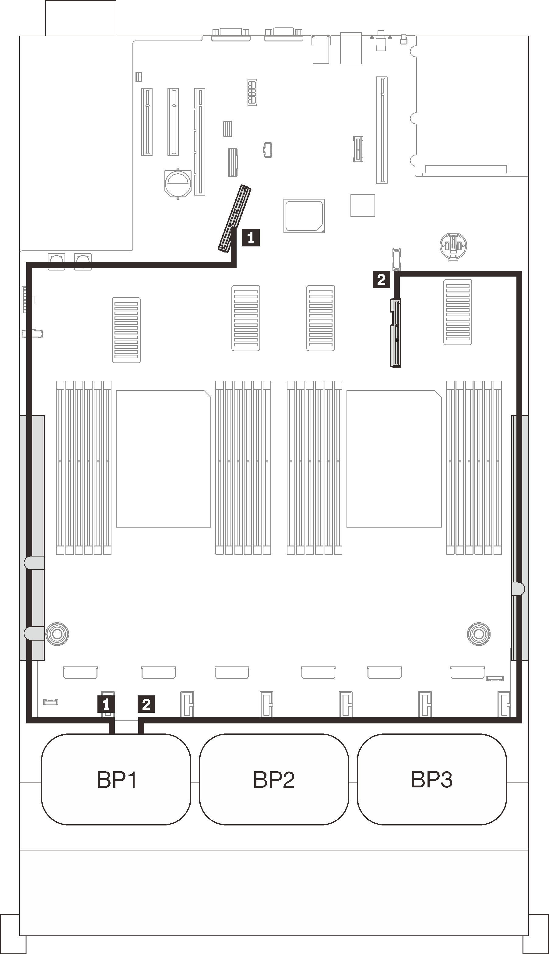
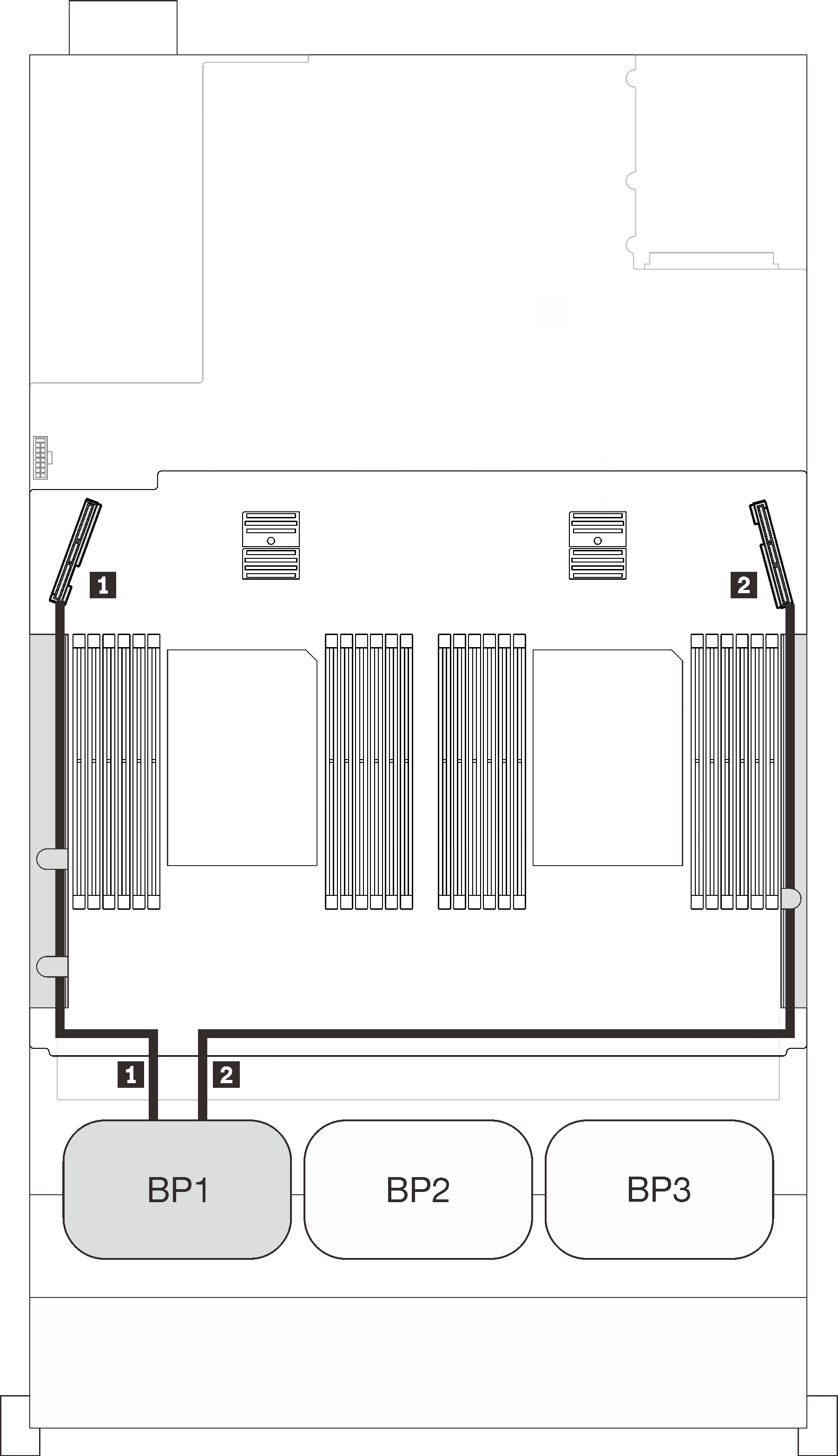
Follow the instructions in this section to learn how do cable routing for pure NVMe backplanes.
Note
- See Connecting cables to the processor and memory expansion tray to perform the procedure properly while connecting PCIe cables to the processor and memory expansion tray.
- See Connecting cables to the NVMe switch cards to perform the procedure properly while connecting PCIe cables to the PCIe switch cards.
See the following sections for cable routing combinations with only NVMe drive backplanes.
One backplane
Two backplanes
Two NVMe backplanes
System board + processor and memory expansion tray
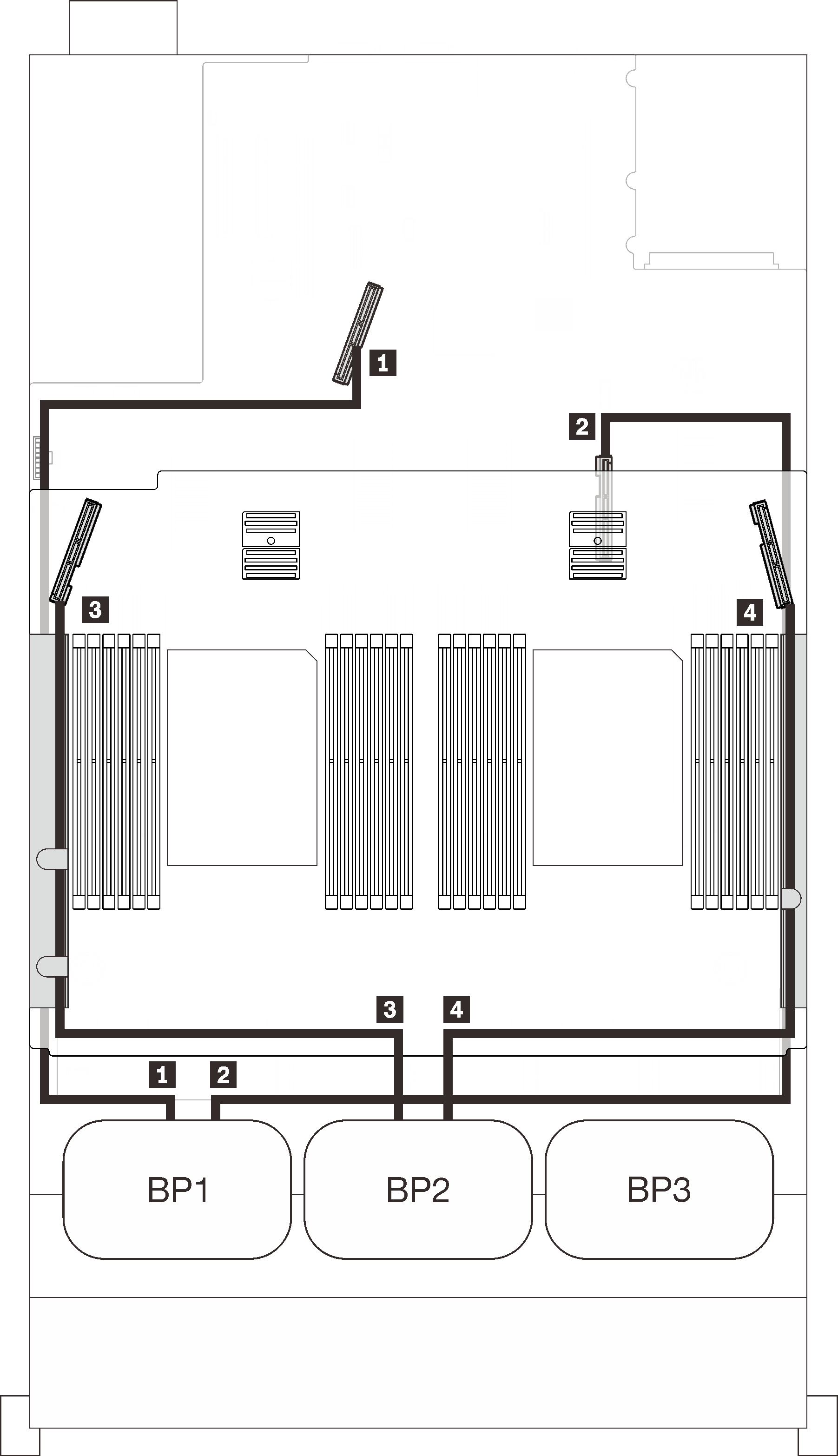 | ||
| PCIe cable routing | ||
| NVMe connector | Length | To |
| 1 0-1, 2-3 | 670 mm | PCIe 1 (on-board) |
| 2 4-5, 6-7 | 910 mm | PCIe 2 (on-board) |
| 3 0-1, 2-3 | 530 mm | PCIe 3 (tray) |
| 4 4-5, 6-7 | 670 mm | PCIe 6 (tray) |
Processor and memory expansion tray + PCIe switch cards
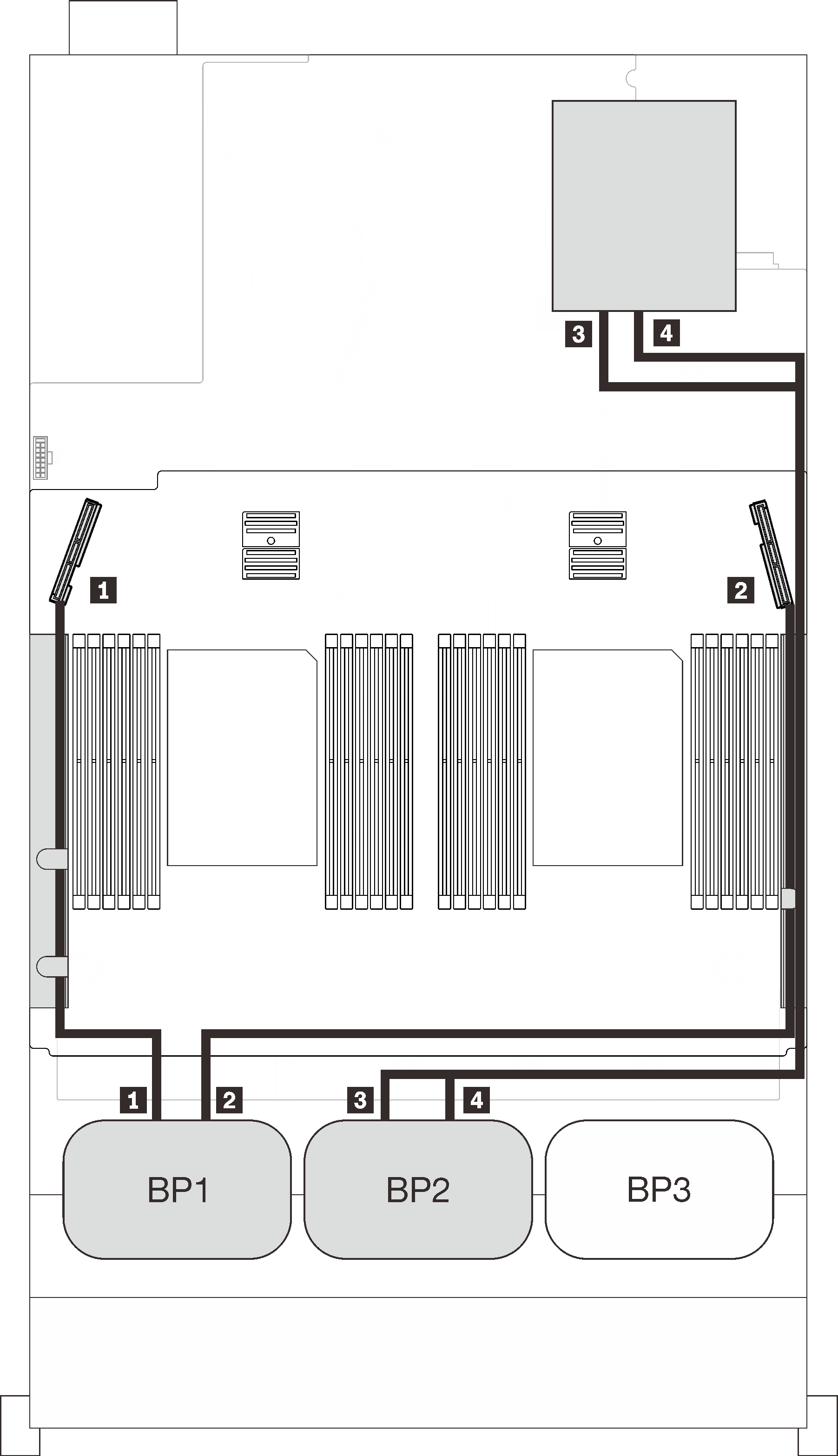 | ||
| PCIe cable routing | ||
| NVMe connector | Length | To |
| 1 0-1, 2-3 | 530 mm | PCIe 3 (tray) |
| 2 4-5, 6-7 | 670 mm | PCIe 6 (tray) |
| 3 0-1, 2-3 | 1100 mm | C0, C1 (Slot 5) |
| 4 4-5, 6-7 | 1100 mm | C0, C1 (Slot 6) |
Three backplanes
Three NVMe backplanes
System board + processor and memory expansion tray + PCIe switch cards
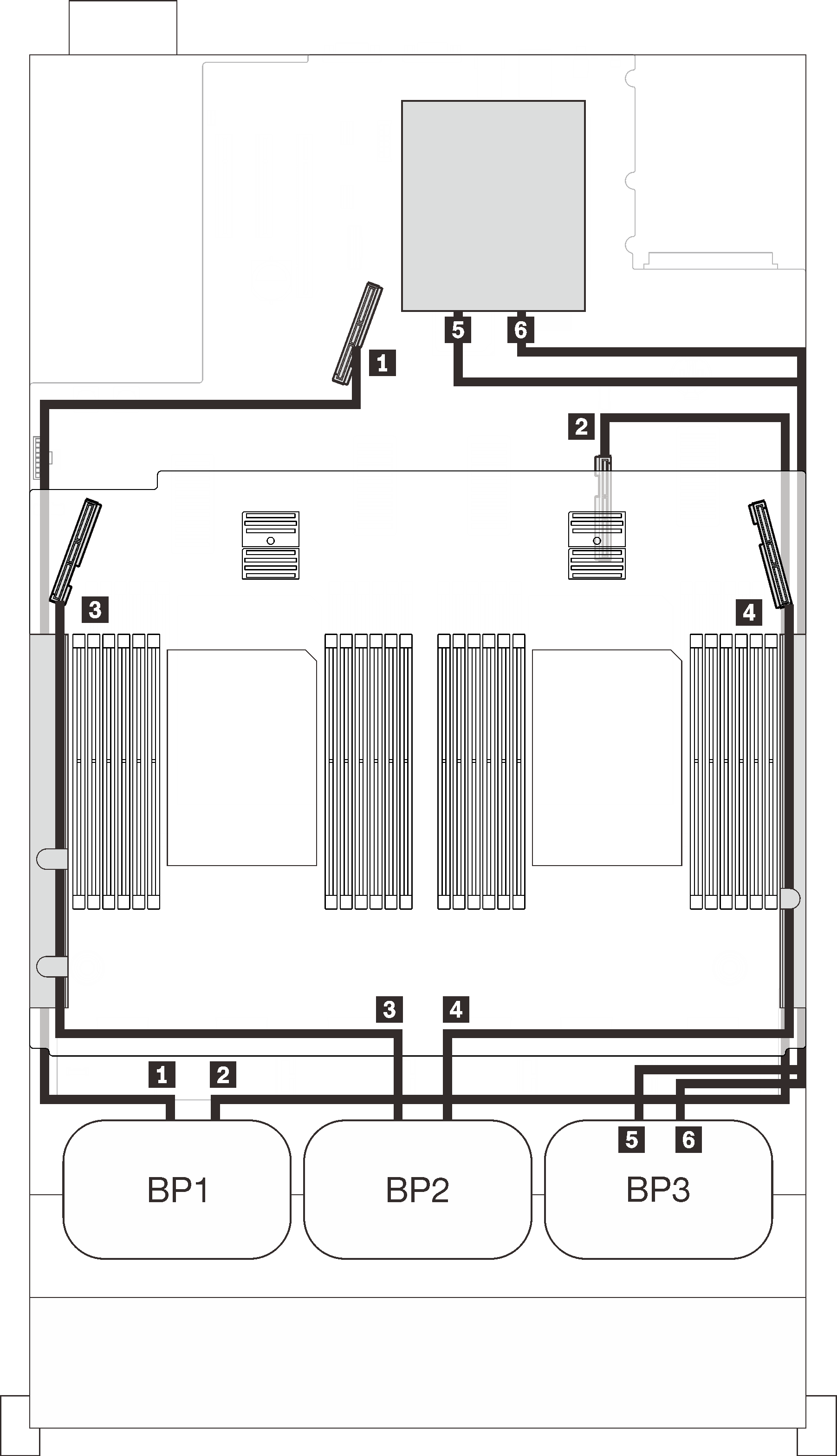 | ||
| PCIe cable routing | ||
| NVMe connector | Length | To |
| 1 0-1, 2-3 | 670 mm | PCIe 1 (on-board) |
| 2 4-5, 6-7 | 910 mm | PCIe 2 (on-board) |
| 3 0-1, 2-3 | 530 mm | PCIe 3 (tray) |
| 4 4-5, 6-7 | 670 mm | PCIe 6 (tray) |
| 5 0-1, 2-3 | 1100 mm | C0, C1 (Slot 5) |
| 6 4-5, 6-7 | 1100 mm | C0, C1 (Slot 6) |
Give documentation feedback
