Install an adapter
Follow the instructions in this section to install an adapter.
About this task
Attention
Go over Installation Guidelines to ensure that you work safely.
Touch the static-protective package that contains the component to any unpainted metal surface on the server; then, remove it from the package and place it on a static-protective surface.
Note
- For a list of supported adapters, see Lenovo ServerProven website.
- The following adapters must be installed in the PCIe riser assembly.
- ThinkSystem Broadcom 57454 10/25GbE SFP28 4-port PCIe Ethernet Adapter
- ThinkSystem Broadcom 57454 10/25GbE SFP28 4-port PCIe Ethernet Adapter V2
- ThinkSystem Broadcom 57504 10/25GbE SFP28 4-port PCIe Ethernet Adapter
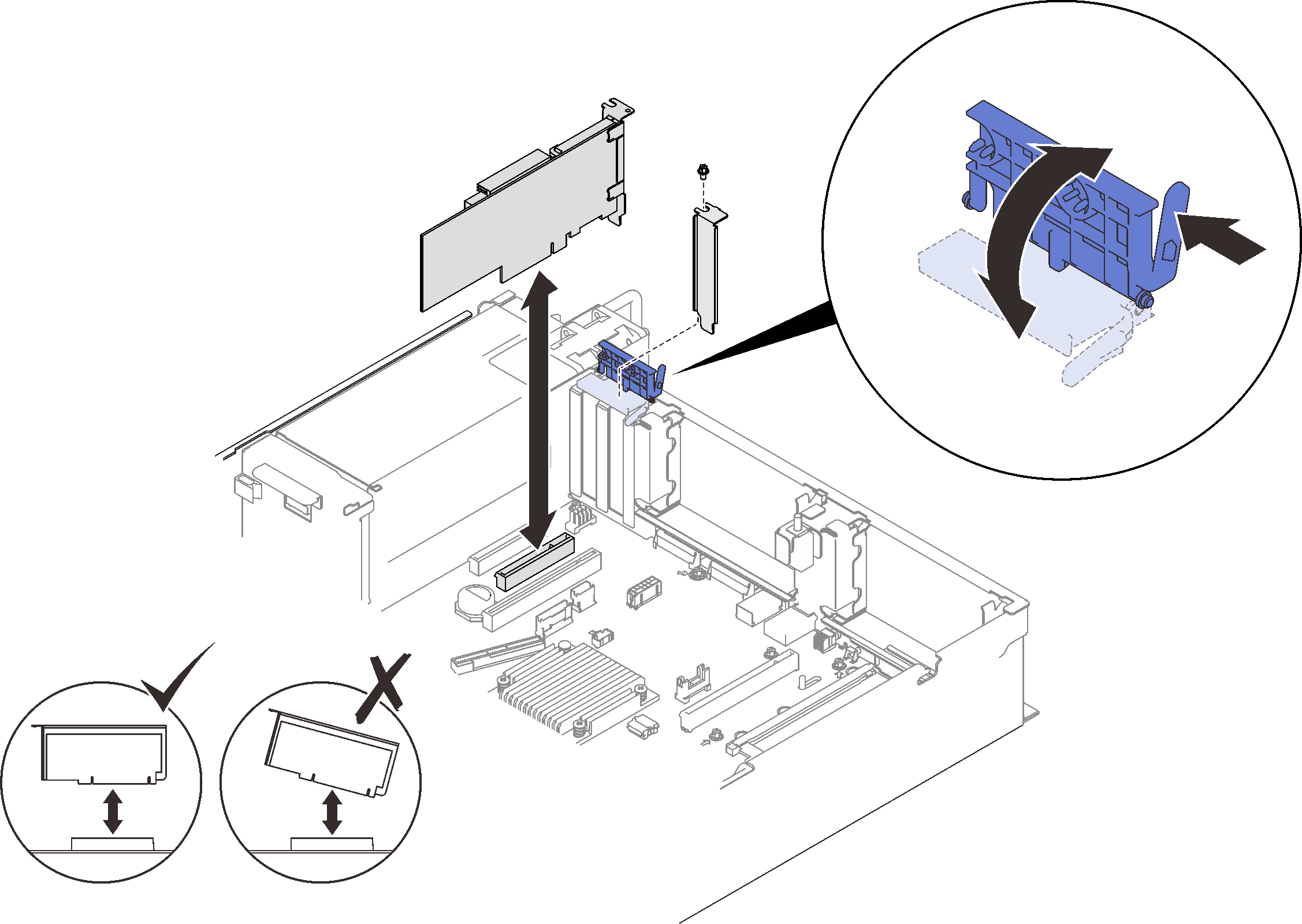
Install an adapter on the system board
Procedure
- Align the adapter with the connector on the system board, and push it in.Figure 1. Installing an adapter to the system board
Install an adapter in the PCIe riser assembly
Important
Make sure to adopt passive Direct Attach cables when ThinkSystem NVIDIA ConnectX-7 adapter is installed.
Note
- When installing the following adapters:
- Nvidia T4
- Mellanox ConnectX-6 HDR 100/100GbE QSFP56 1-port PCIe VPI Adapter
- Mellanox ConnectX-6 HDR 100/100GbE QSFP56 2-port PCIe VPI Adapter
- Mellanox ConnectX-6 HDR/200GbE QSFP56 1-port PCIe 4 VPI Adapter
- ThinkSystem NVIDIA ConnectX-7 NDR200/200GbE QSFP112 2-port PCIe Gen5 x16 InfiniBand Adapter
- ThinkSystem NVIDIA ConnectX-7 NDR400 OSFP 1-Port PCIe Gen5 Adapter
- Zone 1: slot 1 in x16/x16/x16 (x8 lanes) riser
- Zone 2: slot 5 in x16/x16 riser
- When installing two units of Nvidia T4, make sure to meet the following system requirements.
- Maximal capacity of each memory module is 64 GB.
- Maximal quantity depends on processors wattage:
- Less than 165 watts: 48
- 165 to 250 watt: 24
- Maximal quantity of 2.5-inch drives is 16.
- NVMe PCIe 4.0 x8 Flash Adapter has to be installed in slot 1, 5, 7, or 8.
- When Nvidia T4 is installed:
- If OCP Ethernet adapter is installed in slot 4, slot 7 is disabled.
- If an adapter is installed in slot 7, slot 4 is disabled.
- To prevent potential thermal issues, change the Misc setting in the BIOS from Option3 (default value) to Option1 if the following two conditions are met:
The server is equipped with a GPU adapter.
The UEFI firmware version is M5E128A or later.
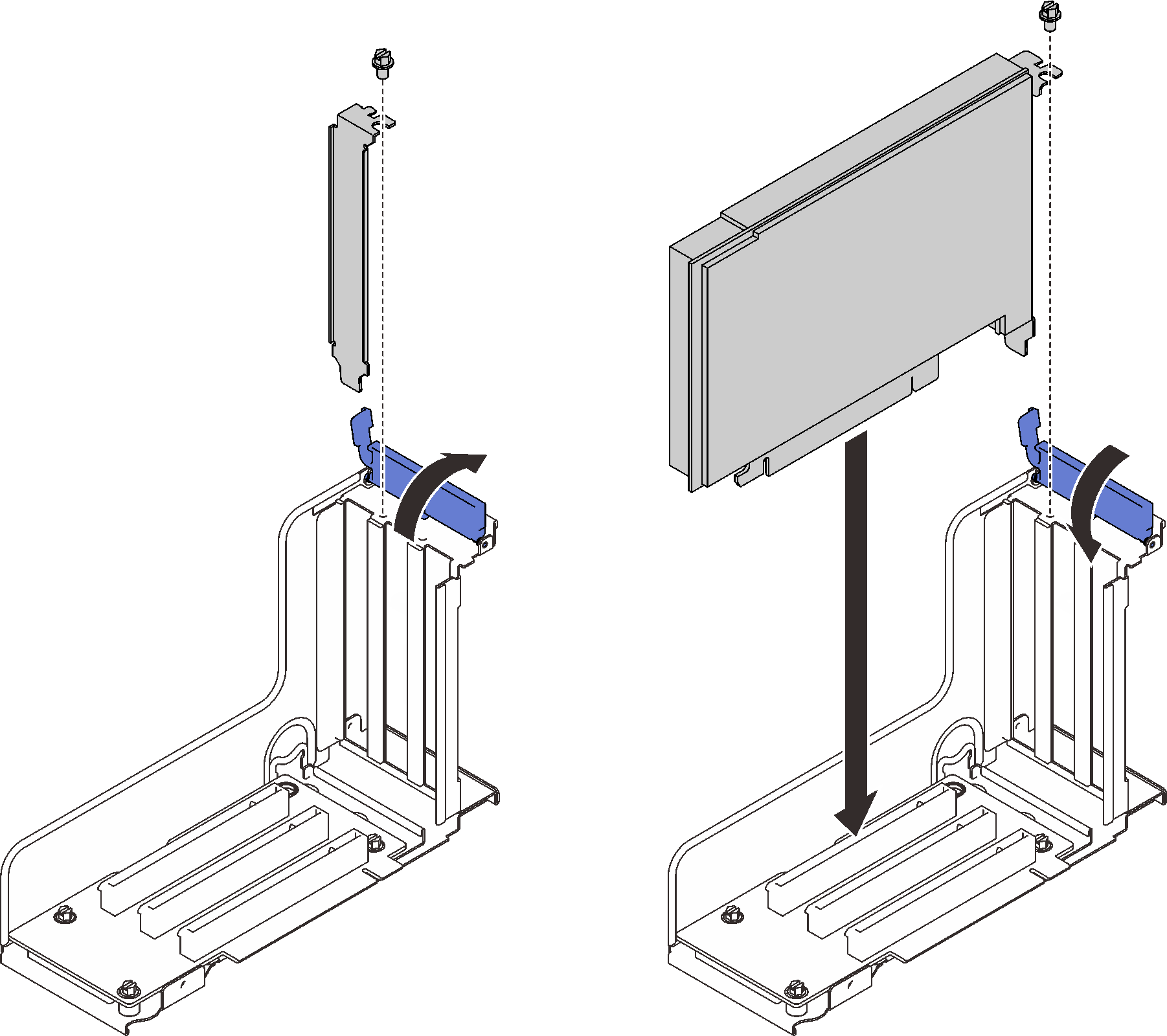
Procedure
- Align the adapter with the connector on the PCIe riser assembly, and push it in.Figure 2. Installing an adapter into the PCIe riser assembly
After this task is completed
- If one of the following adapters has been installed and there is only one or no installed flash power module in the system, install a flash power module (see Install a flash power module).
- ThinkSystem RAID 930-8i 2GB Flash PCIe 12Gb Adapter
- ThinkSystem RAID 930-16i 4GB Flash PCIe 12Gb Adapter
- ThinkSystem RAID 930-8e 4GB Flash PCIe 12Gb Adapte
- ThinkSystem RAID 940-8i 4GB Flash PCIe Gen4 12Gb Adapter
- ThinkSystem RAID 940-8i 8GB Flash PCIe Gen4 12Gb Adapter
- ThinkSystem RAID 940-16i 8GB Flash PCIe 12Gb Adapter
- ThinkSystem RAID 940-32i 8GB Flash PCIe 12Gb Adapter
Proceed to complete the parts replacement (see Complete the parts replacement).
Demo video
Give documentation feedback