Remove the system board
Follow instructions in this section to remove the system board.
- Removing and installing this component requires trained technicians. Do not attempt to remove or install it without proper training.
- When replacing the system board, always update the server with the latest firmware or restore the pre-existing firmware. Make sure that you have the latest firmware or a copy of the pre-existing firmware before you proceed.
Go over Installation Guidelines to ensure that you work safely.
Turn off the server and peripheral devices and disconnect the power cords and all external cables (see Power off the server).
If the server is installed in a rack, slide the server out on its rack slide rails to gain access to the top cover, or remove the server from the rack.
Procedure
- Disengage the system board.Figure 1. Disengaging the system board
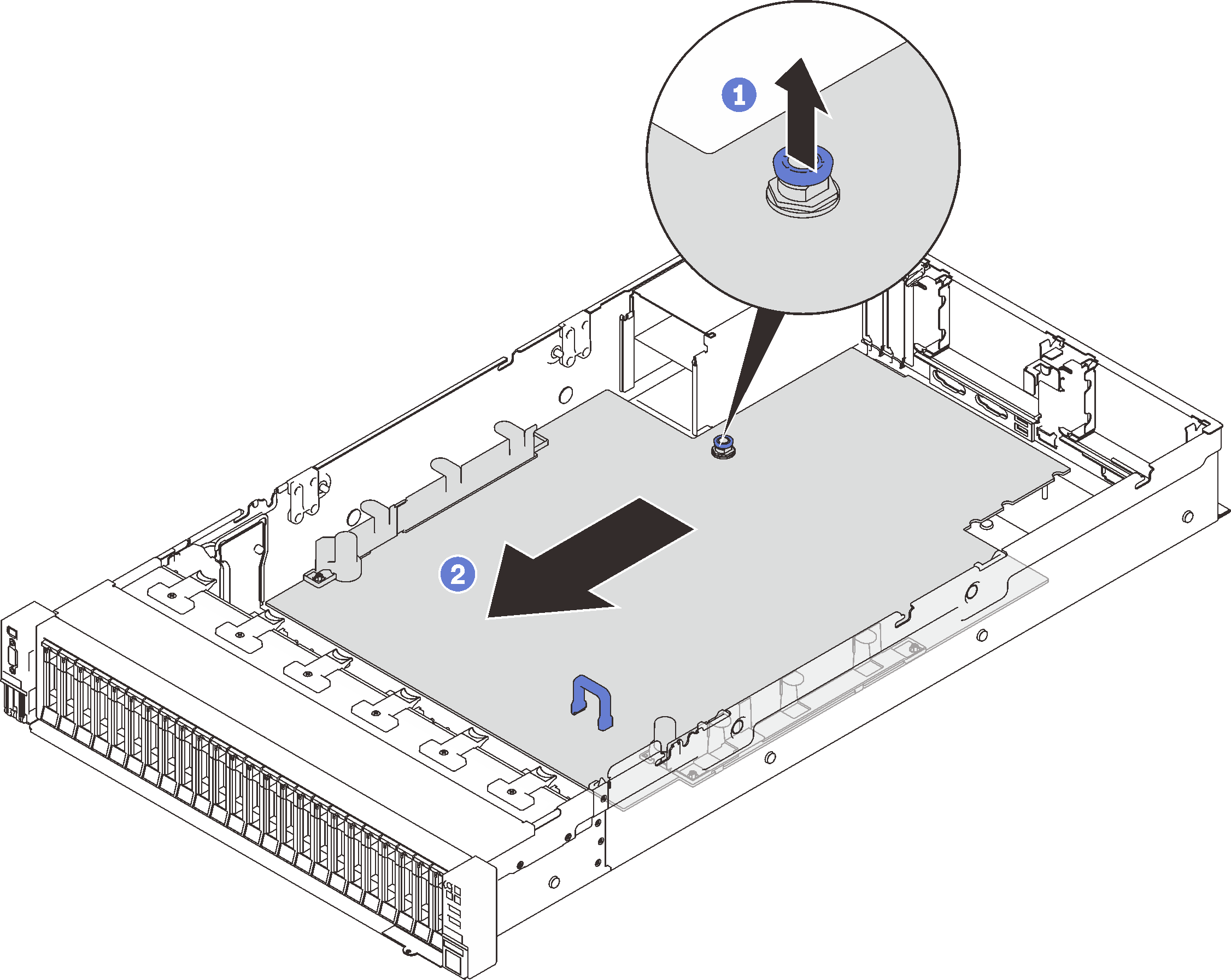
 Pull the captive screw up to release the system board.
 Grasp the blue handle, and slide the system board back slightly to disengage it from the chassis.
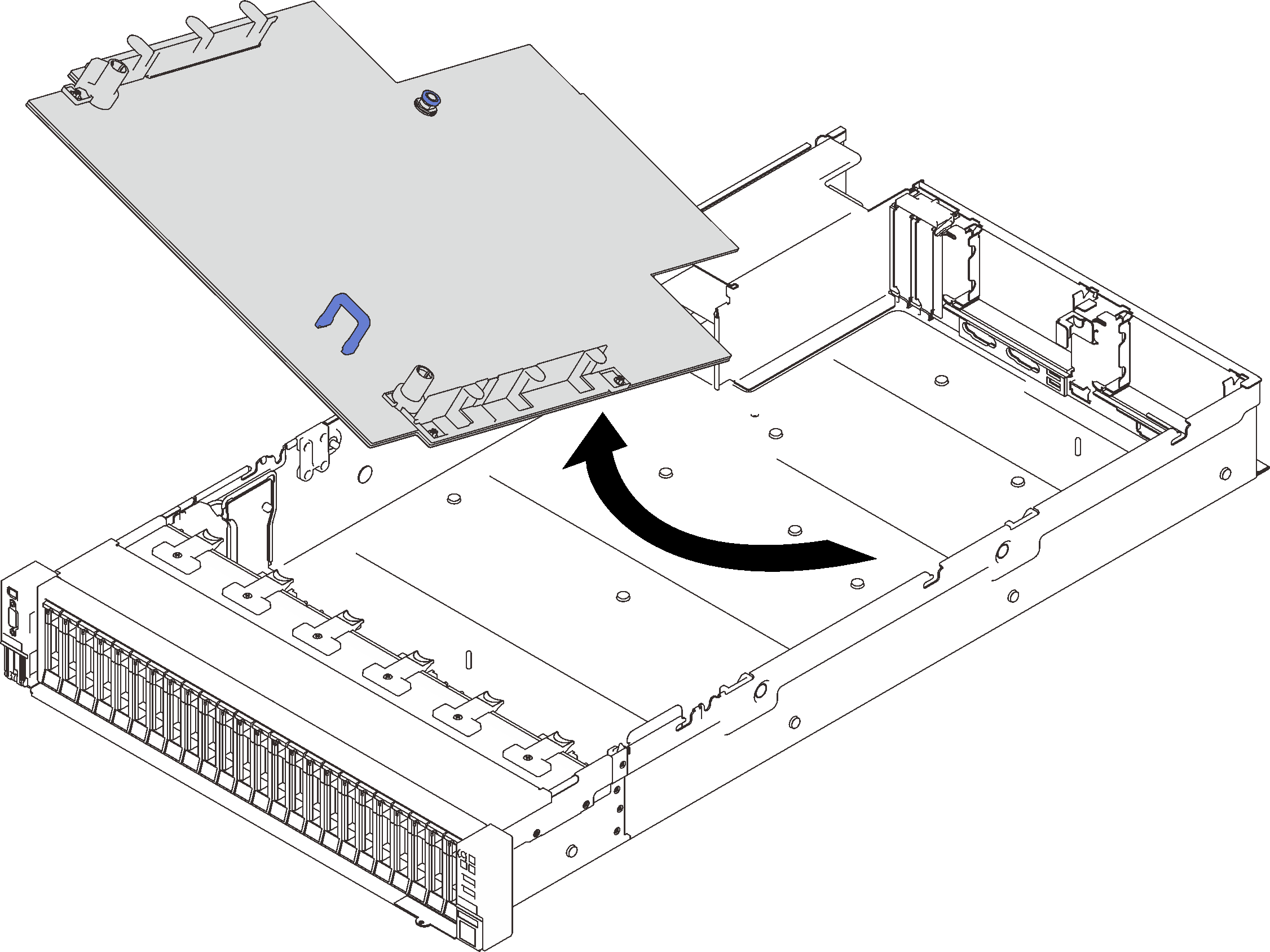
NoteThis handle only serves the purpose of removing system board. Do not attempt to lift the whole server with it. - Slide the system board left and up, and remove it from the chassis.Figure 2. Removing the system board
After this task is completed
If you are instructed to return the component or optional device, follow all packaging instructions, and use any packaging materials for shipping that are supplied to you.
ImportantBefore returning the system board, make sure that you install the processor socket dust covers from the new system board. To replace a processor socket dust cover:Take a dust cover from the processor socket assembly on the new system board, and orient it correctly above the processor socket assembly on the removed system board.
Gently press down the dust cover legs to the processor socket assembly, pressing on the edges to avoid damage to the socket pins. You might hear a click on the dust cover is securely attached.
Make sure that the dust cover is securely attached to the processor socket assembly.
- If you are planning to recycle the system board, follow the instructions in Disassemble the system board for recycle for compliance with local regulations.
Demo video
Disassemble the system board for recycle
Follow the instructions in this section to disassemble the processor and memory expansion tray before recycle.
About this task
Go over Installation Guidelines to ensure that you work safely.
Turn off the server and peripheral devices and disconnect the power cords and all external cables (see Power off the server).
If the server is installed in a rack, slide the server out on its rack slide rails to gain access to the top cover, or remove the server from the rack.
- Remove the following components as illustrated:
22 slotted screws
Two standoffs (with 12 mm wrench)
One plunger (with 11 mm and 16 mm wrench)
Figure 3. Disassembling the system board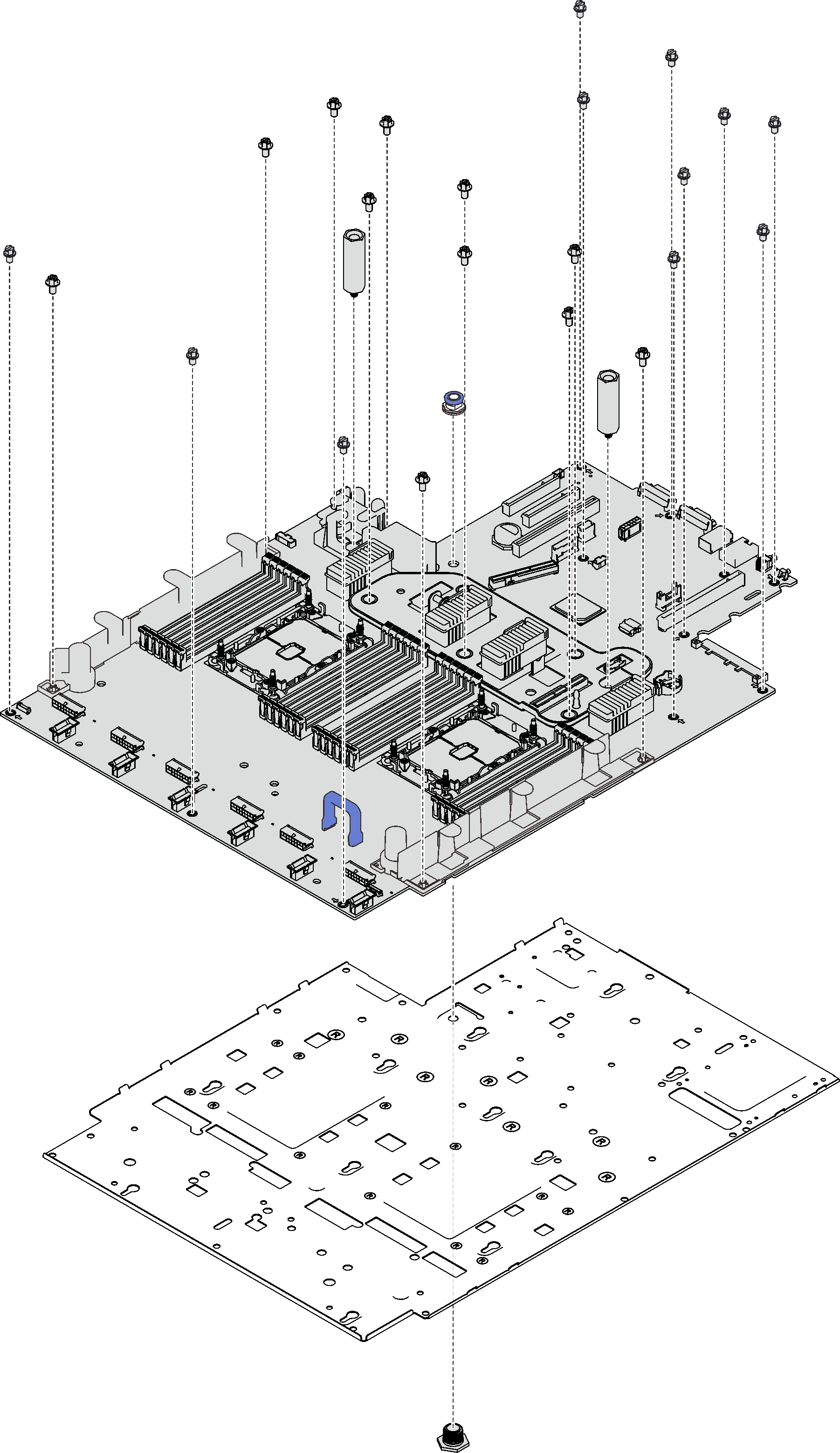
After this task is completed
Recycle the unit in compliance with local regulations.