
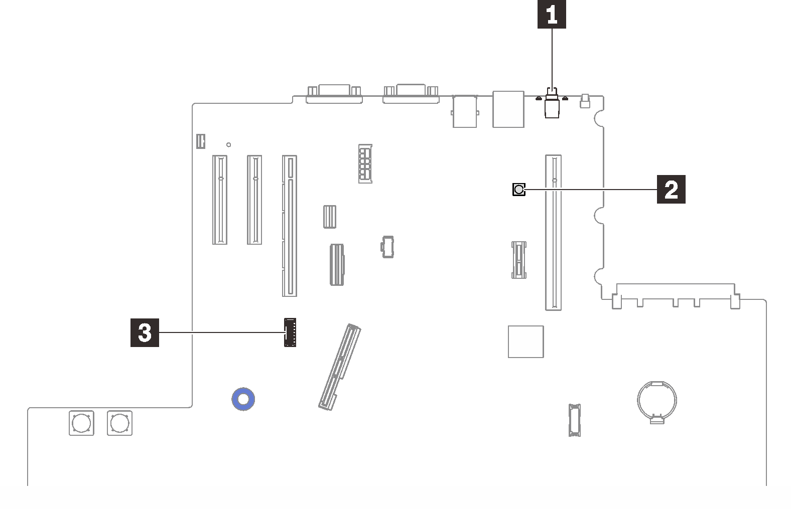
Switches, jumpers, and buttons

The following illustration shows the location of the switches, jumpers, and buttons on the server.

Note
If there is a clear protective sticker on the top of the switch block, you must remove and discard it to access the switch.
Figure 1. Switches, jumpers and buttons

NMI button

Table 1. NMI button
Button nameFunction
Force NMI buttonThis button is on the rear of the server. Press this button to force a nonmaskable interrupt to the processor. You might have to use a pen or the end of a straightened paper clip to press the button. You can also use it to force a blue screen memory dump (use this button only when you are directed to do so by Lenovo Support).

Light path button

Table 2. Light path button
Button nameFunction
Light path buttonPress this button to light the LEDs on the system board when the power source has been removed from the server.

SW4

See the following table for SW4 switch block functions.

Table 3. System board SW4 switch block descriptions
Switch numberDefault positionOffOn
1, 16OffHost TPM Physical Presence disabledHost TPM Physical Presence enable
2, 15OffPASSWORD_OVERRIDE function disabledPASSWORD_OVERRIDE function enabled
3, 14OffSerial port message from uEFISerial port message from Lenovo XClarity Controller
4, 13OffXCC TPM Physical Presence disabledXCC TPM Physical Presence enabled
5, 12OffManaging Engine recovery mode disabledManaging Engine set to recovery mode
6, 11OffManaging Engine security override disabledManaging Engine security override enabled
7, 10OffReserved
8, 9Off Real time clock reset
Important
  1. Before you change any switch settings or move any jumpers, turn off the server; then, disconnect all power cords and external cables. Review the information in Safety Information page, Installation Guidelines, Handling static-sensitive devices, and Power off the server.
  2. Any system board switch or jumper block that is not shown in the illustrations in this document are reserved.