Front I/O module
The front I/O module of the server provides controls, connectors, and LEDs. The front I/O module varies by model.
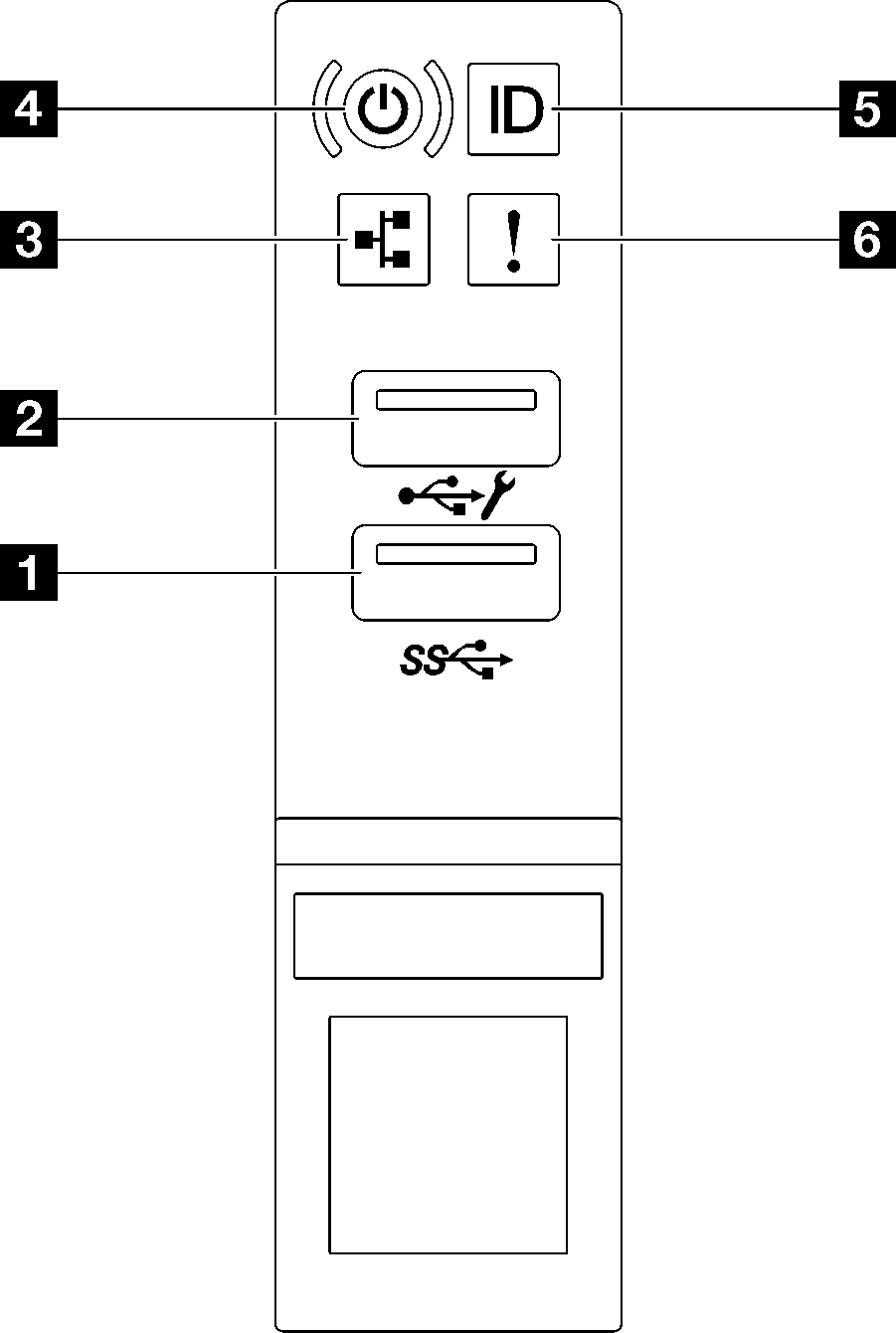
| 1 USB 3.1 Gen 1 (5 Gbps) connector | 4 Power button/LED (green) |
| 2 USB 2.0 connector with Lenovo XClarity Controller management | 5 System ID button/LED (blue) |
| 3 Network Activity LED (green) | 6 System error LED (yellow) |
1 USB 3.1 Gen 1 (5 Gbps) connector
The USB 3.1 Gen 1 (5 Gbps) connector can be used to attach a USB-compatible device, such as a USB keyboard, USB mouse, or USB storage device.
2 USB 2.0 connector with Lenovo XClarity Controller management
Connection to Lenovo XClarity Controller is primarily intended for users with a mobile device running the Lenovo XClarity Controller mobile application. When a mobile device is connected to this USB port, an Ethernet over USB connection is established between the mobile application running on the device and the Lenovo XClarity Controller.
Select Network in BMC Configuration to view or modify settings.
Four types of settings are available:
- Host only mode
In this mode, the USB port is always solely connected to the server.
- BMC only mode
In this mode, the USB port is always solely connected to Lenovo XClarity Controller.
- Shared mode: owned by BMC
In this mode, connection to the USB port is shared by the server and Lenovo XClarity Controller, while the port is switched to Lenovo XClarity Controller.
- Shared mode: owned by host
In this mode, connection to the USB port is shared by the server and Lenovo XClarity Controller, while the port is switched to the server.
3 Network Activity LED (green)
| Status | Color | Description |
|---|---|---|
| On | Green | The server is connected to a network. |
| Blinking | Green | The network is connected and active. |
| Off | None | The server is disconnected from the network. |
4 Power button/LED (green)
| Status | Color | Description |
|---|---|---|
| Off | None | Power is not present, or the power supply has failed. |
| Fast blinking (about four flashes per second) | Green |
|
| Slow blinking (about one flash per second) | Green | The server is off and is ready to be powered on (standby state). |
| Solid on | Green | The server is on and running. |
5 System ID button/LED (blue)
Use this system ID button and the blue system ID LED to visually locate the server. Each time you press the system ID button, the state of the system ID LED changes. The LED can be changed to on, blinking, or off. You can also use the Lenovo XClarity Controller or a remote management program to change the state of the system ID LED to assist in visually locating the server among other servers.
6 System error LED (yellow)
| Status | Color | Description | Action |
|---|---|---|---|
| On | Yellow | An error has been detected on the server. Causes might include one or more of the following errors:
| Check the Event log to determine the exact cause of the error. |
| Off | None | The server is off or the server is on and is working correctly. | None. |