Install a drive backplane
Use this procedure to install a drive backplane.
Before installing a drive backplane:
Read the safety information and installation guidelines (see Safety and Installation Guidelines).
Touch the static-protective package that contains the component to any unpainted metal surface on the server; then, remove it from the package and place it on a static-protective surface.
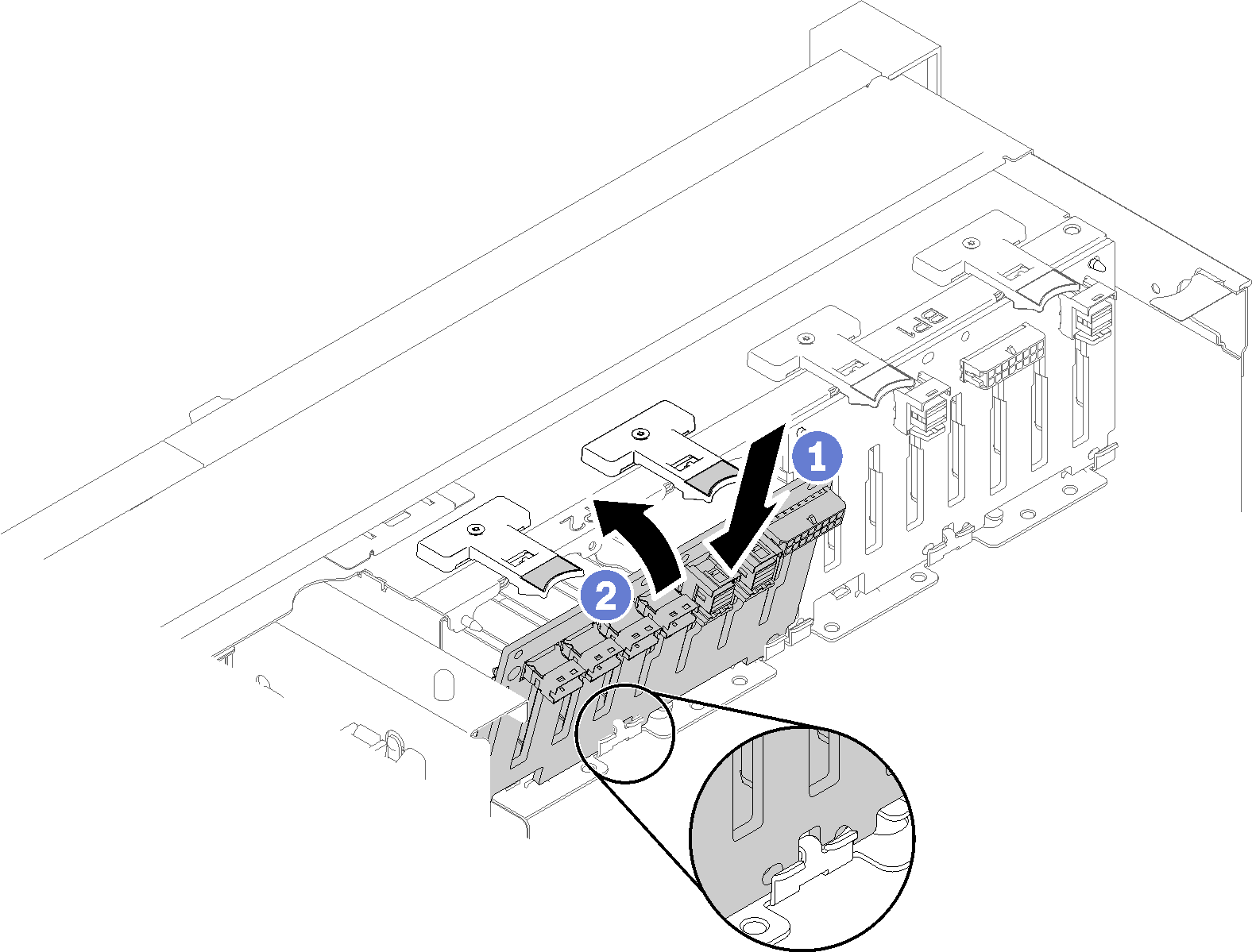
To install a drive backplane, complete the following steps:
- Push the top of the drive backplane toward the front of the server until it clicks in place.Figure 1. Drive backplane installation
- Apply drive bay labels based on the type of backplane installed. Several drive bay labels come with each type of the supported drive backplane:
8-bay backplane
12-15 (NVMe)
Apply this label to drive bay 12-15 if an AnyBay backplane is installed to drive bay 8-15.
12-15
Apply this label to drive bay 12-15 if an 8-bay backplane is installed to drive bay 8-15
4-7
Apply this label to drive bay 4-7 if an 8-bay backplane is installed to drive bay 0-7.
AnyBay backplane
4-7 (NVMe)
Apply this label to drive bay 4-7 if an AnyBay backplane is installed to drive bay 0-7.
12-15 (NVMe)
Apply this label to drive bay 12-15 if an AnyBay backplane is installed to drive bay 8-15.
NoteOnly drive bay 4-7 and 12-15 may support NVMe solid-state drives when AnyBay backplane is installed. Drive bay 0-3 and 8-11 always support SATA/SAS drives only.
Figure 2. Drive bay labels of NVMe solid-state drives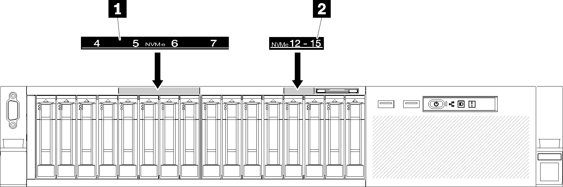
Table 1. Drive bay labels of NVMe solid-state drives 1 Drive bay 4-7 label of NVMe solid-state drives 2 Drive bay 12-15 label of NVMe solid-state drives
After installing the drive backplane, complete the following steps:
Connect the cables to the drive backplane. If the type of drive backplane is changed, it is necessary to reroute the signal cables (see Cable routing for 2.5-inch drives for detailed instructions).
Install the drives (see Install a 2.5-inch hot-swap drive).
If the system board air baffle or the processor and memory expansion tray and expansion tray air baffle have been removed, install them (see Install the system board air baffle and the power interposer or Install the processor and memory expansion tray).
Reinstall the top cover (see Install the top cover).
Reconnect the power cords and any cables that you removed.
Install the server in the rack.
Power on the server and any peripheral devices.
Demo video