Optional processor and memory expansion tray
Use this information to locate the connectors and LEDs on the optional processor and memory expansion tray.
The following illustrations show the connectors and LEDs on the processor and memory expansion tray.
Figure 1. Optional processor and memory expansion tray
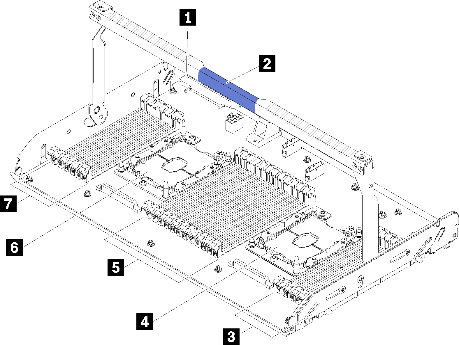
| 1 Power supply 2 connector | 5 DIMM slot 31-42 |
| 2 Tray handle | 6 Processor 3 |
| 3 DIMM slot 43-48 | 7 DIMM slot 25-30 |
| 4 Processor 4 |
Figure 2. LEDs on the optional processor and memory expansion tray
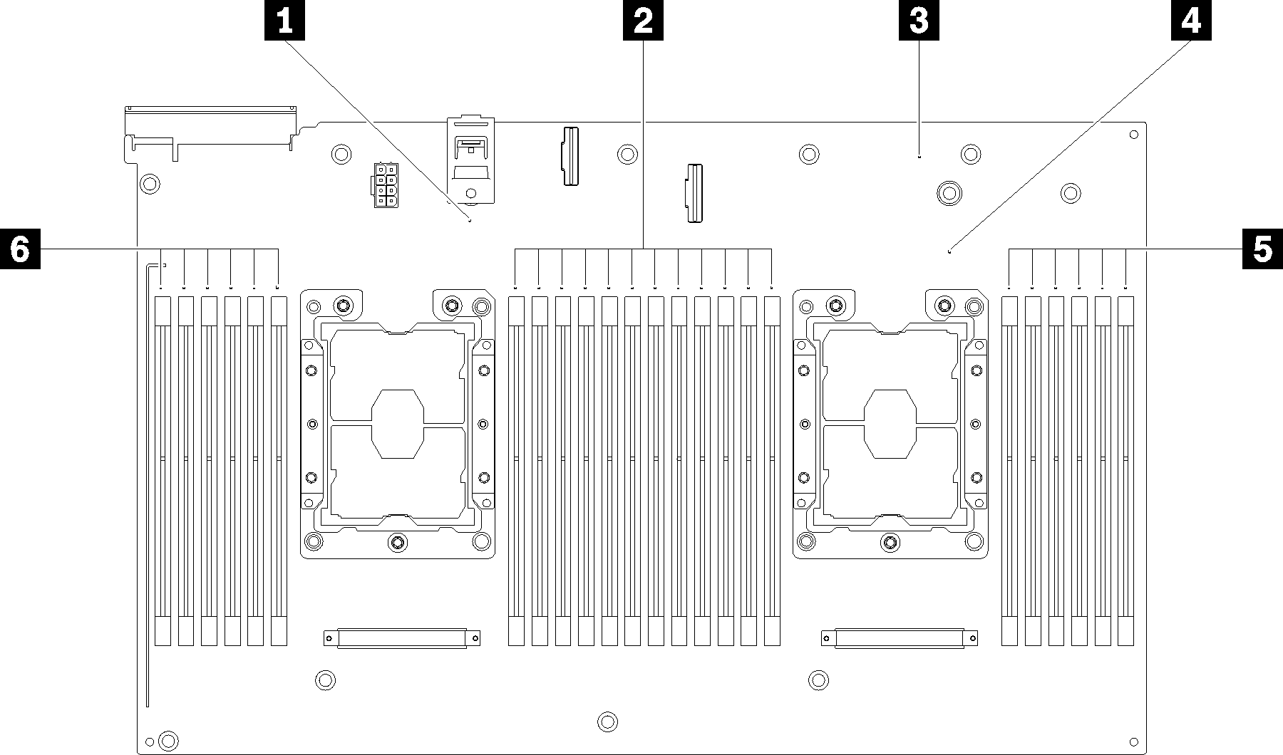
| 1 Processor 3 error LED | 4 Processor 4 error LED |
| 2 DIMM slot 31-42 error LEDs | 5 DIMM slot 43-48 error LEDs |
| 3 Expansion board error LED | 6 DIMM slot 25-30 error LEDs |
Figure 3. Connectors on the optional processor and memory expansion tray
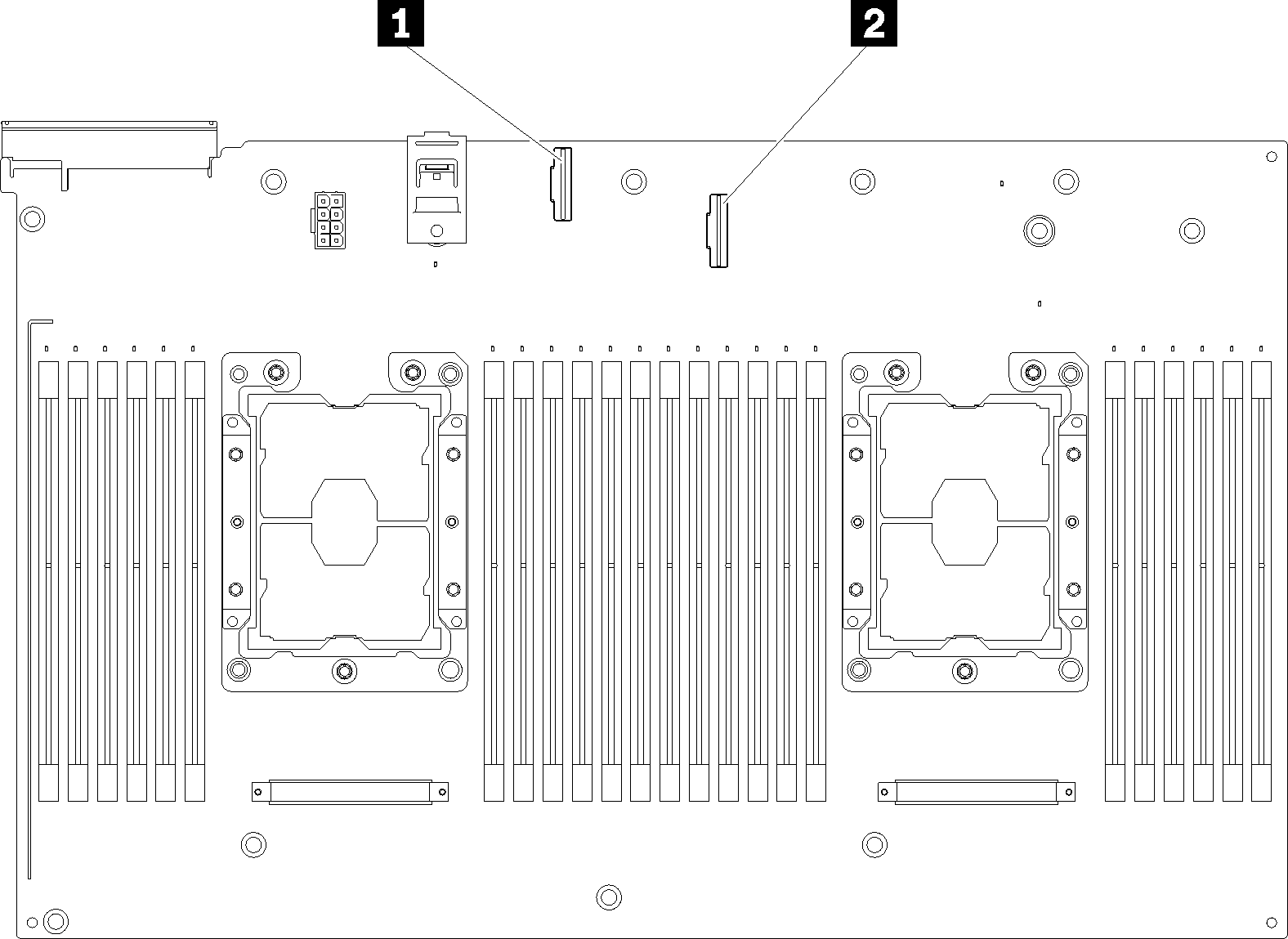
| 1 NVMe signal cable connector 0-1 | 2 NVMe signal cable connector 2-3 |
Give documentation feedback