Rear view
This section contains information about the LEDs and connectors on the rear of the server.
The following illustrations show the connectors and LEDs on the rear of the server.
There are two sections show the different components on the rear server, see section Connectors and LEDs on the rear server and section Expansion slots on the rear server for more information.
Connectors and LEDs on the rear server
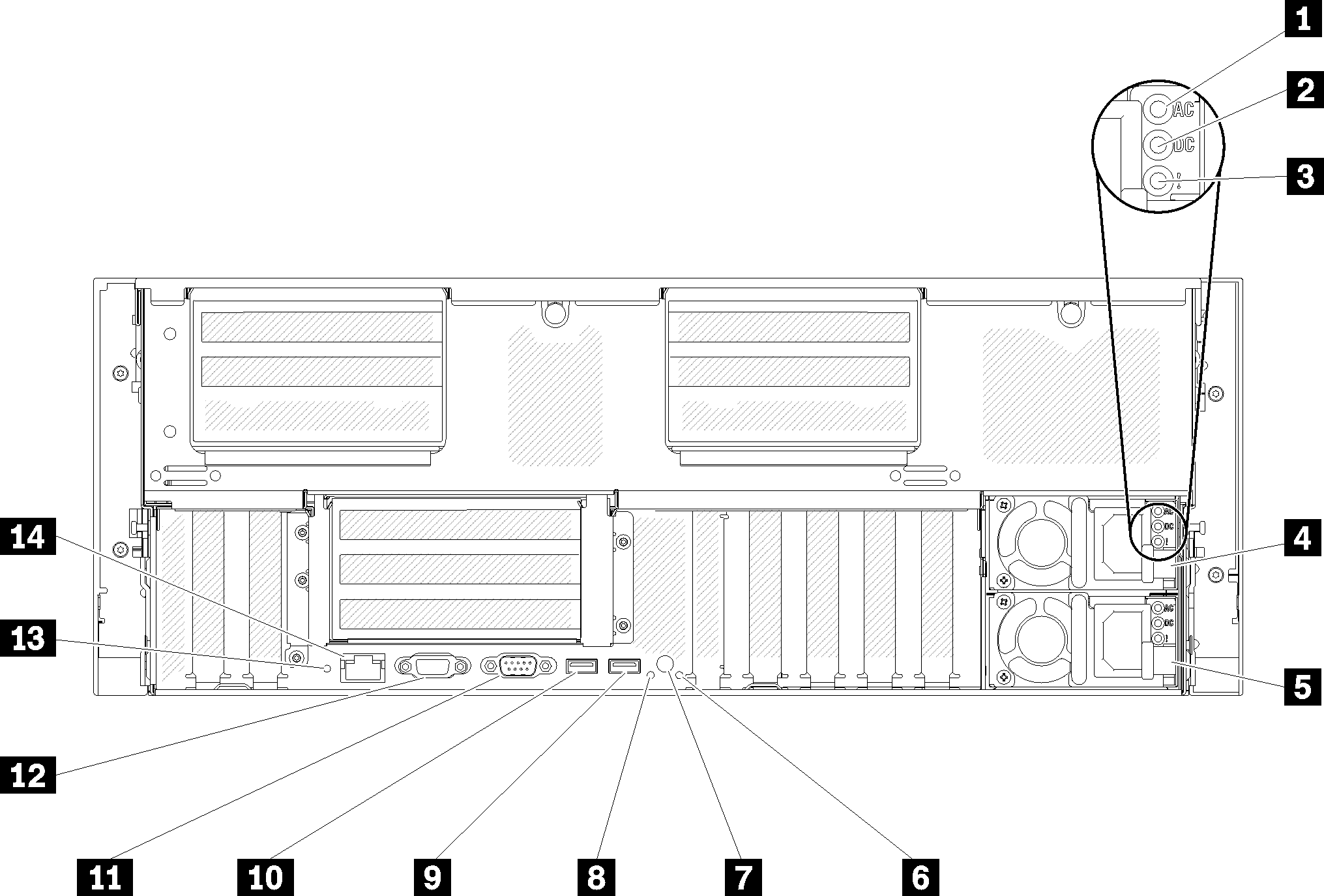
| 1 AC power LED (green) | 8 Identification LED (blue) |
| 2 DC power LED (green) | 9 USB 4 (USB 3.0) |
| 3 Power supply error LED (yellow) | 10 USB 3 (USB 3.0) |
| 4 Power supply unit 2 | 11 Serial connector |
| 5 Power supply unit 1 | 12 VGA connector |
| 6 System error LED (yellow) | 13 NMI button |
| 7 Identification button | 14 Lenovo XClarity Controller network connector |
1 AC power LED:
Each hot-swap power supply comes with an AC power LED and a DC power LED. When the AC power LED is lit, it indicates that sufficient power is being supplied to the power supply through the power cord. During normal operation, both the AC and DC power LEDs are lit. For more information, see Light path diagnostics.
2 DC power LED:
Each hot-swap power supply comes with a DC power LED and an AC power LED. When the DC power LED is lit, it indicates that the power supply is supplying adequate DC power to the system. During normal operation, both the AC and DC power LEDs are lit. For more information, see Light path diagnostics.
3 Power-supply error LED:
When the power-supply error LED is lit, it indicates that the power supply has failed.
4 5 Power supply units:
Install power supply units to these bays, connect them to power cords. Make sure the power cords are connected properly. Following are the power supplies supported by this system:
- 750-watt platinum power supply
- input power 115V or 230V ac
- 1100-watt platinum power supply
- input power 115V or 230V ac
- 1600-watt platinum power supply
- input power 230V ac
- 2000-watt platinum power supply
- input power 230V ac
6 System error LED (yellow):
When this yellow LED is lit, it indicates that a system error has occurred. This LED can be controlled by the Lenovo XClarity Administrator. Information provided from the LCD display of the front operator panel could also help isolate an error.
7 Identification button:
This button is functionally equivalent to the identification button on the front of the server.
8 Identification LED (blue):
Use this LED to visually locate the server among other servers. You can use Lenovo XClarity Controller to turn this LED on and off. This LED is functionally equivalent to the identification LED on the front of the server.
9 10 USB connectors (USB 3.0):
Connect a USB device, such as a USB mouse, keyboard, or other device, to any of these connectors.
11 Serial connector:
Connect a 9-pin serial device to this connector. The serial port is shared with the Lenovo XClarity Controller. The Lenovo XClarity Controller can take control of the shared serial port to redirect serial traffic, using Serial over LAN (SOL).
12 VGA connector:
- When the front VGA connector is in use, the rear VGA connector will be disabled.
- The maximum video resolution is 1920 x 1200 at 60 Hz.
13 NMI button:
Press this button to force a nonmaskable interrupt to the processor. You might have to use a pen or the end of a straightened paper clip to press the button. You can also use it to force a blue-screen memory dump. Use this button only when you are directed to do so by Lenovo Support.
14 Lenovo XClarity Controller network connector:
Use this connector to manage the server, by using a dedicated management network. If you use this connector, the Lenovo XClarity Controller cannot be accessed directly from the production network. A dedicated management network provides additional security by physically separating the management network traffic from the production network. You can use the Setup utility to configure the server to use a dedicated systems-management network or a shared network.
Expansion slots on the rear server
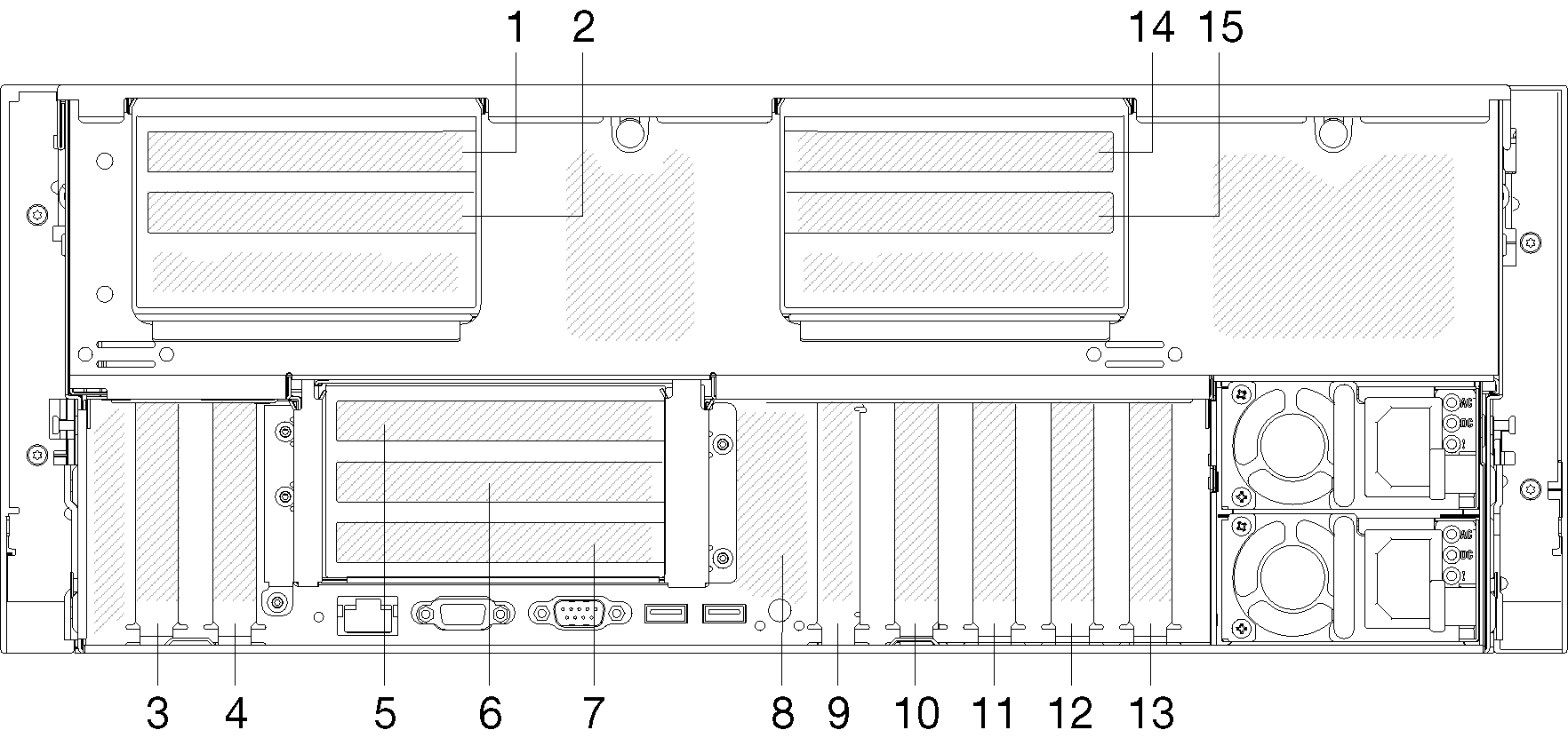
PCIe slot 1 and 2 (on 4U PCIe riser assembly 2):
PCIe slot 1 and 2 are available with a 4U PCIe riser card installed in slot 3. Following are the 4U PCIe riser cards supported by this server.
- ThinkSystem SR860 2x8 PCIe FH riser 2 provides:
- Slot 1: PCI Express 3.0 x8
- Slot 2: PCI Express 3.0 x8
Note:The PCIe riser card uses x16 mechanical connectors with x8 signals.
The riser card supports HBA and network/RAID adapter with external connection.
- ThinkSystem SR860 1x16 PCIe FH riser 2 provides:
- Slot 1: GPU
- Slot 2: Not available in the riser card
- ThinkSystem SR860 2x8 PCIe FH riser 2 provides:
PCIe slot 3:
PCI Express 3.0 x16 (supports PCIe switch card, not available after the 4U PCIe riser card installed)
PCIe slot 4:
PCI Express 3.0 x8 (supports RAID adapters for SATA/SAS drives)
PCIe slot 5 - 7 (on PCIe riser card 1):
Install a full-height PCIe riser card into this slot. Following are the PCIe riser cards supported by this server.- x8/x8/x8 PCIe full-height riser assembly provides:
- Slot 5: PCI Express 3.0 x8 (network adapters with RJ45 connectors are not supported)
- Slot 6: PCI Express 3.0 x8
- Slot 7: PCI Express 3.0 x8
- x8/x8/x8 ML2 PCIe full-height riser assembly provides:
- Slot 5: PCI Express 3.0 x8 (network adapters with RJ45 connectors are not supported)
- Slot 6: PCI Express 3.0 x8
- Slot 7: Customized slot for x8 ML2 adapter
- x8/x16 ML2 PCIe full-height riser assembly provides:
- Slot 5: PCI Express 3.0 x8 (network adapters with RJ45 connectors are not supported)
- Slot 6: Not available in the riser card
- Slot 7: Customized slot for x16 ML2 adapter
- x8/x8/x8 PCIe full-height riser assembly provides:
M.2 backplane (slot 8):
Install M.2 backplane to this slot. See M.2 drive and backplane replacement for more details.
LOM adapter (slot 9):
Insert LOM adapter into this slot (see System-board connectors for the location of the LOM adapter slot on the system board and LOM adapter replacement for information about the installation of the LOM adapter).
PCIe slot 10:
PCI Express 3.0 x8
PCIe slot 11:
PCI Express 3.0 x8
PCIe slot 12:
PCI Express 3.0 x8 supports RAID adapters for SATA/SAS drives
PCIe slot 13:
PCI Express 3.0 x16 (supports PCIe switch card, not available after the 4U PCIe riser card installed)
PCIe slot 14 and 15 (on 4U PCIe riser assembly 3):
PCIe slot 14 and 15 are available with a 4U PCIe riser card installed in slot 13. Following are the 4U PCIe riser cards supported by this server.
- ThinkSystem SR860 2x8 PCIe FH riser 3 provides:
- Slot 14: PCI Express 3.0 x8
- Slot 15: PCI Express 3.0 x8
Note:The PCIe riser card uses x16 mechanical connectors with x8 signals.
The riser card supports HBA and network/RAID adapter with external connection.
- ThinkSystem SR860 1x16 PCIe FH riser 3 provides:
- Slot 14: GPU
- Slot 15: Not available in the riser card
- ThinkSystem SR860 2x8 PCIe FH riser 3 provides: