Front view
This section contains information about the controls, LEDs, and connectors on the front of the server.
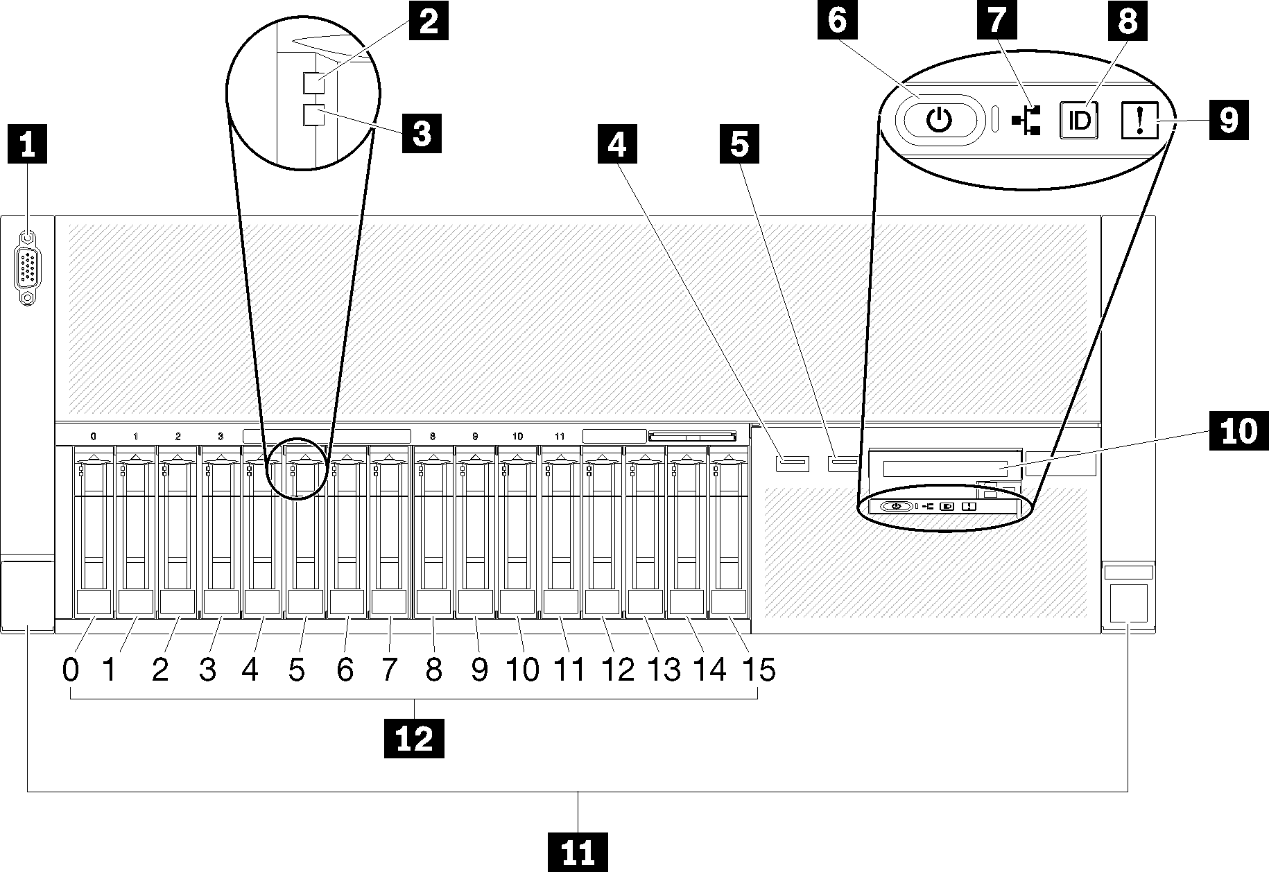
| 1 VGA connector | 7 Network activity LED (green) |
| 2 Drive activity LED (green) | 8 Identification button/LED (blue) |
| 3 Drive status LED (yellow) | 9 System error LED (yellow) |
| 4 USB 1 (USB 2.0 with Lenovo XClarity Controller management) | 10 Front operator panel with optional pull-out LCD display |
| 5 USB 2 | 11 Rack release latches |
| 6 Power button/LED (green) | 12 2.5-inch drive bays |
1 VGA connector:
- When the front VGA connector is in use, the rear VGA connector will be disabled.
- The maximum video resolution is 1920 x 1200 at 60 Hz.
2 Drive activity LED (green):
Each hot-swap drive comes with an activity LED, and when this LED is flashing, it indicates that the drive is in use.
3 Drive status LED (yellow):
These LEDs are on SAS or SATA hard disk drives and solid-state drives. When one of these LEDs is lit, it indicates that the drive has failed. When this LED is flashing slowly (one flash per second), it indicates that the drive is being rebuilt. When the LED is flashing rapidly (three flashes per second), it indicates that the controller is identifying the drive.
4 5 USB connectors:
USB 1: USB 2.0 with Lenovo XClarity Controller management
USB 2: USB 2.0 or 3.0 (depending on the model)
6 Power button/LED (green):
- Off: No power supply is properly installed, or the LED itself has failed.
- Flashing rapidly (4 times per second): The server is turned off and is not ready to be turned on. The power-control button is disabled. This will last approximately 5 to 10 seconds.
- Flashing slowly (once per second): The server is turned off and is ready to be turned on. You can press the power-control button to turn on the server.
- Solid on: The server is turned on.
7 Network activity LED (green):
When this LED is lit, it indicates that the server is transmitting to or receiving signals from the Ethernet LAN.
8 Identification button/LED (blue):
Press this button to visually locate the server among other servers. Use this LED to visually locate the server among other servers. You can use Lenovo XClarity Controller to turn this LED on and off.
9 System error LED (yellow):
When this yellow LED is lit, it indicates that a system error has occurred. This LED can be controlled by the Lenovo XClarity Administrator. Information provided from the LCD display of the front operator panel could also help isolate an error.
10 Front operator panel with optional pull-out LCD display:
This panel contains controls and LEDs that provide information about the status of the server.
11 Rack release latches:
Press the latch on both sides in the front of the server to remove the server out of the rack.
12 2.5-inch drive bays:
Install 2.5-inch drives to these bays. See Install a 2.5-inch hot-swap drive for more details.