System-board connectors
Use this information to locate the system-board internal connectors.
Figure 1. System-board connectors
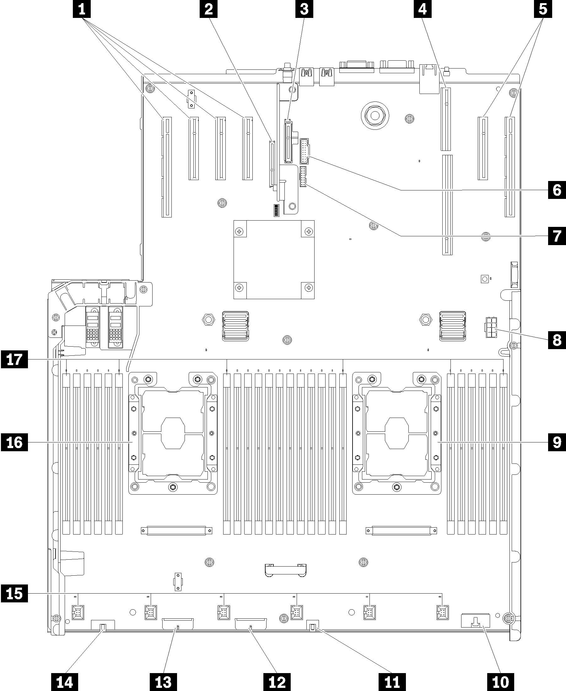
| 1 PCIe slot 13, 12, 11, 10 | 10 Front operator panel connector |
| 2 PCIe slot 9 (LOM adapter) | 11 USB 1 (USB 2.0 with Lenovo XClarity Controller management) |
| 3 PCIe slot 8 (M.2 backplane) | 12 Backplane connector 2 |
| 4 PCIe slot 5-7 (PCIe riser card 1) | 13 Backplane connector 1 |
| 5 PCIe slot 4, 3 | 14 Front VGA connector |
| 6 USB 2 (USB 3.0) | 15 Fan connector 1-6 |
| 7 TCM module | 16 Processor 1 |
| 8 Auxiliary power connector | 17 DIMM slot 1-6, 7-18, 19-24 |
| 9 Processor 2 |
Give documentation feedback