Configuration 3. Four-Socket Upgradable
The ThinkSystem SR950 is available in several configurations.
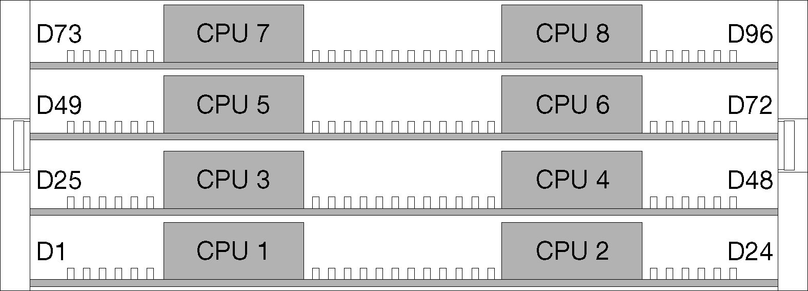
2 or 4 processors, must be 8100 Series processors
4 processors in a ring topology
12 drive bays including up to 6 NVMe (2 NVMe with 2 processors)
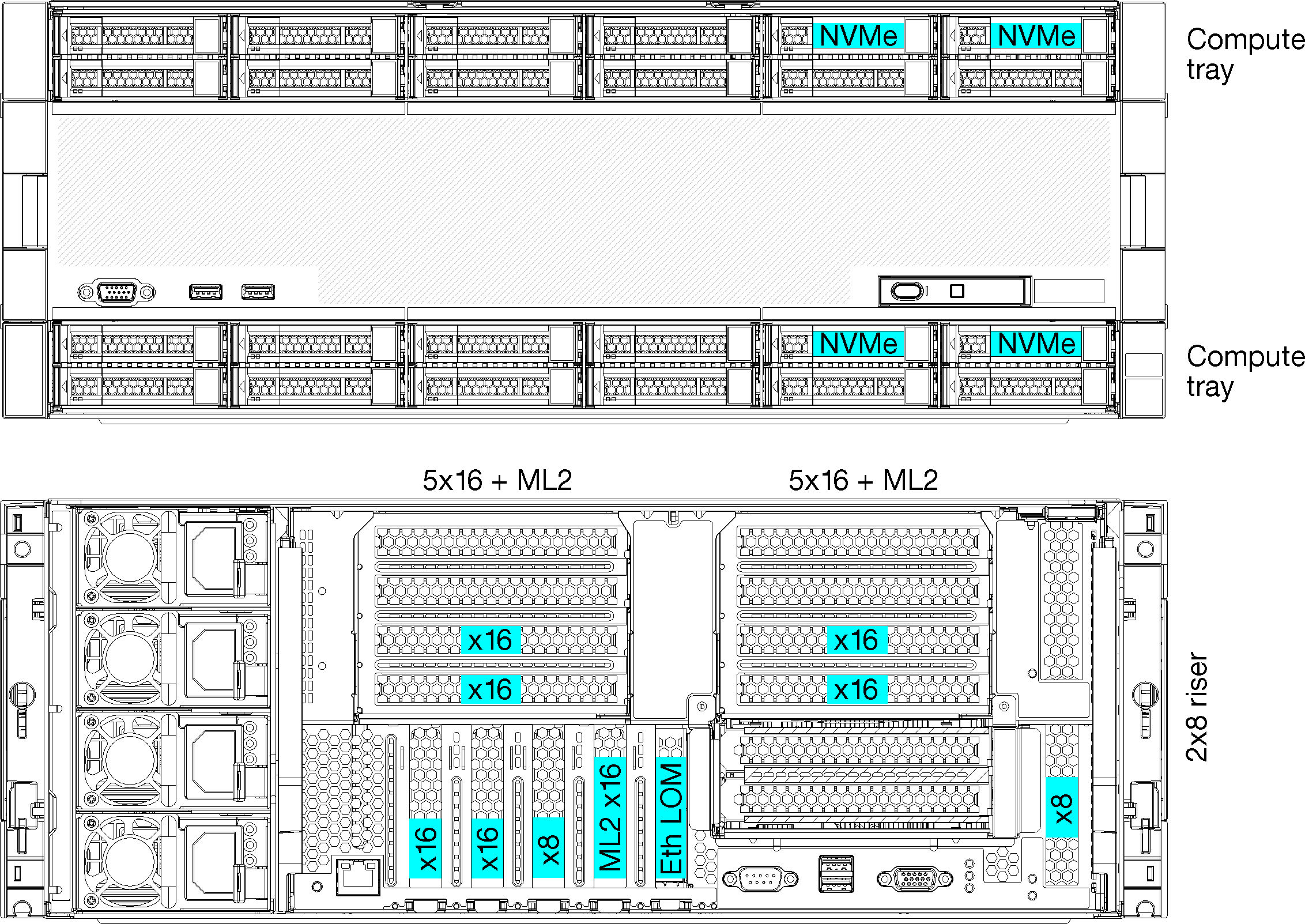
Up to 15 rear PCIe slots with 4 processors (6 rear slots with 2 processors)
Filler installed in the upper tray area
Upgradable to 8-socket with an additional compute tray and two system boards
Once upgraded, the system will have 24 drive bays
Processor configurations
2-processor configuration. Processors are installed in location 1 and 2.
4-processor configuration. Processors are installed in locations 1, 2, 3, and 4.
PCIe slot connectivity
| PCIe slot | Slot location | Description |
|---|---|---|
| 1 | Riser 1 | 41 Not connected for 2x16. Slots 1 and 2 are not connected if the 2x16 riser is used in riser slot 1 |
| 2 | 41 Not connected for 2x16. Slots 1 and 2 are not connected if the 2x16 riser is used in riser slot 1 | |
| 3 | 41 | |
| 4 | 41 | |
| 5 | I/O tray | 2 |
| 6 | 2 | |
| 7 | 1 | |
| 8 (ML2) | 1 | |
| 9 (LOM) | 1 (PCH) | |
| 10 | Riser 2 | 32 |
| 11 | 32 | |
| 12 | 32 | |
| 13 | 32 | |
| 14 | Not connected. | |
| 15 (ML2) | Not connected. | |
| 16 | 2x8 Riser | 32 |
| 17 | 1 | |
| M.2 | I/O tray | 1 (PCH) |
| Storage adapter | Upper tray | Not connected. |
| Storage adapter | Lower tray | 1 |
Note
| ||
Drive bays
Drives are all located at the front of the server, 12 drives at the front of the upper tray and 12 at the front of the lower tray. Drives are connected to 4-drive backplanes in a 2-by-2 configuration, as shown in the following figure. All drive bays are 2.5-inch form factor.
SAS/SATA backplane: Supports 4 SAS or SATA drives
AnyBay backplane:
Top two drives support SAS, SATA, or NVMe interface drives (Lenovo AnyBay). The server can support up to 12 NVMe drives, depending on the server configuration. The NVMe-capable drive bays are the even-numbered bays as shown in Figure 2.
Bottom two drive bays support SAS or SATA drives only
Regular 2.5-inch SAS/SATA drive bays support only SAS or SATA drives; however, the Lenovo AnyBay drive bay design allows a choice of SATA, SAS, or U.2 (NVMe) PCIe drives. This design enables the flexibility to configure some of the bays with high-performance PCIe SSDs while still using the other bays for high-capacity HDDs, which is an ideal solution for storage-tiering.
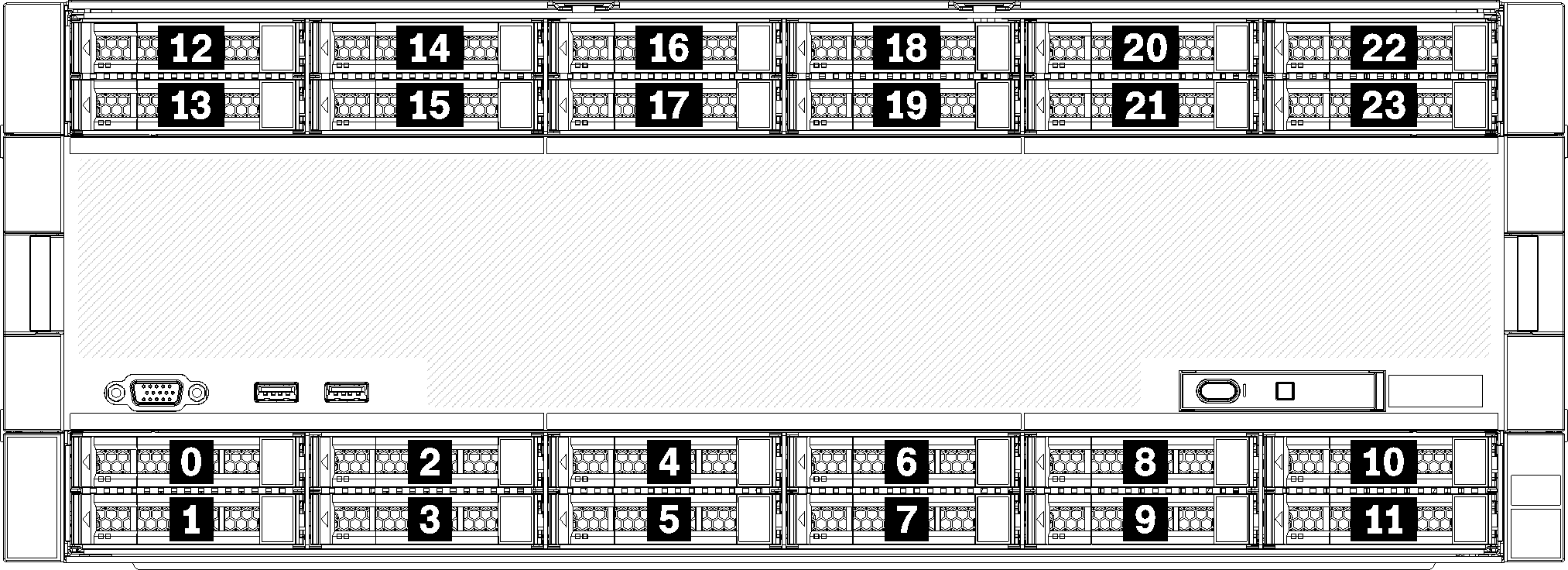
| Installed processors | Maximum storage | Location of NVMe drives (see Figure 2) |
|---|---|---|
| 2 | 12 drives (2 NVMe drives) | Bays 8 and 10 |
| 4 | 12 drives (6 NVMe drives) | Bays 0, 2, 4, 6, 8, 10 |