
Installing the 4S Performance to 8S Upgrade Kit

A ThinkSystem SR950 server with a four-socket performance configuration can be upgraded with the 4S Performance to 8S Upgrade Kit to support an eight-socket configuration. The installation of this conversion kit must be done by a trained service technician.

The 4S Performance to 8S Upgrade Kit includes the following parts:
  • Four midplanes (interconnect cards)

  • Nine Torx-head screws (you will use eight screws, but an extra screw is included in case it is needed)

Important
The 4S Performance to 8S Upgrade Kit enables the ThinkSystem SR950 server to support eight processors. However, extra processors do not come with the conversion kit; you are responsible for purchasing the desired number and type of processors. If you install the conversion kit, all processors in the server must be 8100 Series processors.
S002
disconnect all power
CAUTION
The power-control button on the device and the power switch on the power supply do not turn off the electrical current supplied to the device. The device also might have more than one power cord. To remove all electrical current from the device, ensure that all power cords are disconnected from the power source.
S014
shock hazard
CAUTION
Hazardous voltage, current, and energy levels might be present. Only a qualified service technician is authorized to remove the covers where the label is attached.
S037
mechanical lift required
CAUTION
The weight of this part or unit is more than 55 kg (121.2 lb). It takes specially trained persons, a lifting device, or both to safely lift this part or unit.
S036


18 - 32 kg (39 - 70 lb)32 - 55 kg (70 - 121 lb)
CAUTION
Use safe practices when lifting.
CAUTION
Make sure that all server power cords are disconnected from their power sources before performing this procedure.

The process for installing the conversion kit requires that you remove the existing midplanes (interconnect cards) in the server and replace them with the midplanes provided in the conversion kit. In addition, an upper compute tray must installed in the server to take advantage of all eight processors.

The following illustration identifies the various midplanes that might be installed in your server.

Figure 1. Midplane identification
Midplane removal
Table 1. Midplanes
Icon A 
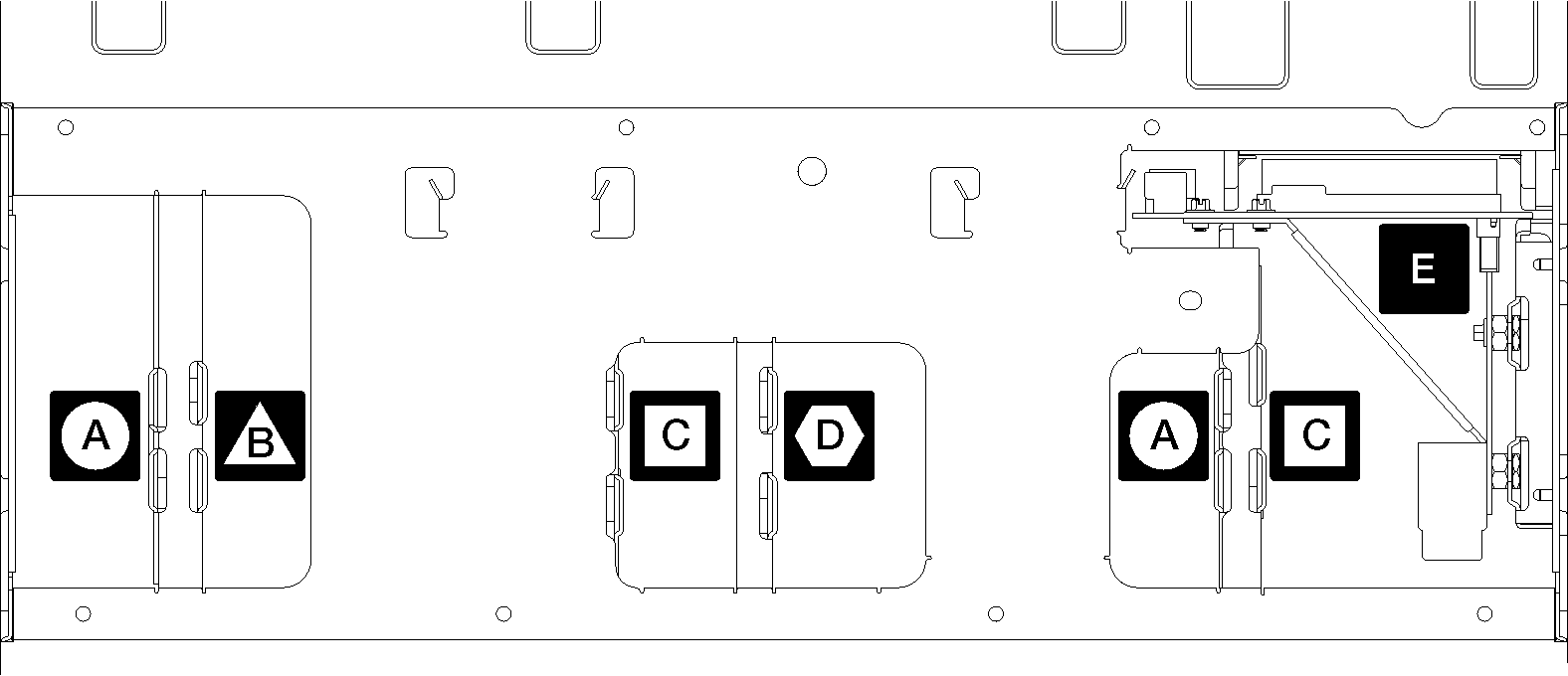
Midplane used in four-socket storage rich configurationsIcon D Midplane used in four-socket and eight-socket configurations

The 4S Performance to 8S Upgrade Kit comes with one of these midplanes.

Icon B Midplane used in four-socket and eight-socket configurations

The 4S Performance to 8S Upgrade Kit comes with one of these midplanes.

Icon E Power midplane used in all server configurations
Icon C Midplane used in four-socket and eight-socket configurations

The 4S Performance to 8S Upgrade Kit comes with two of these midplanes.


Complete the following steps to install the 4S Performance to 8S Upgrade Kit:

  1. Make sure that the server is powered off and disconnected from power source.
  2. Disconnect all the external cables.
  3. Remove the front cover. See Remove the front cover.
  4. Make sure that all the trays, including compute trays, storage tray, and the I/O tray are removed from the server.
  5. If the server is in a rack, remove it from the rack.

    See the ThinkSystem SR950 Rack Installation Instructions, which is available here:

    Resources and downloads

  6. Remove the midplanes from the server (depending on the configuration, you might need to remove up to 6 midplanes). You must remove midplanes A (if installed), B, C, and D. However, you do not need to remove the power midplane (midplane E). See Figure 1 for the locations of all the midplanes.

    Instructions for removing the midplanes are available here:

    Remove a midplane

    Note
    When you remove the top cover, discard the screws. Use the Torx-head screws that are provided with the conversion kit instead (eight screws and an extra screw are included).
  7. Install the midplanes that are provided with the conversion kit. Install only midplane B, C, and D.
    Note
    Two midplane C interconnect cards are provided in the conversion kit. Make sure to install both of them.

    Instructions for installing the midplanes are available here:

    Install a midplane

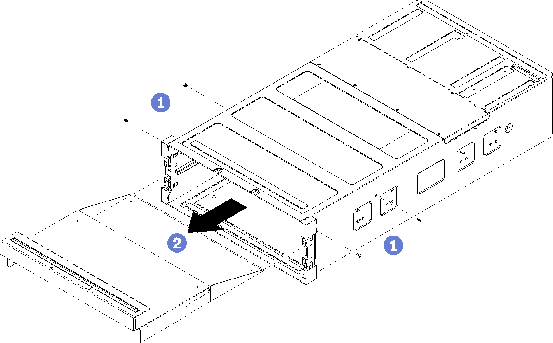
  8. If a filler is installed in the upper tray bay, you must remove it and install a compute tray to enable eight-socket capability.

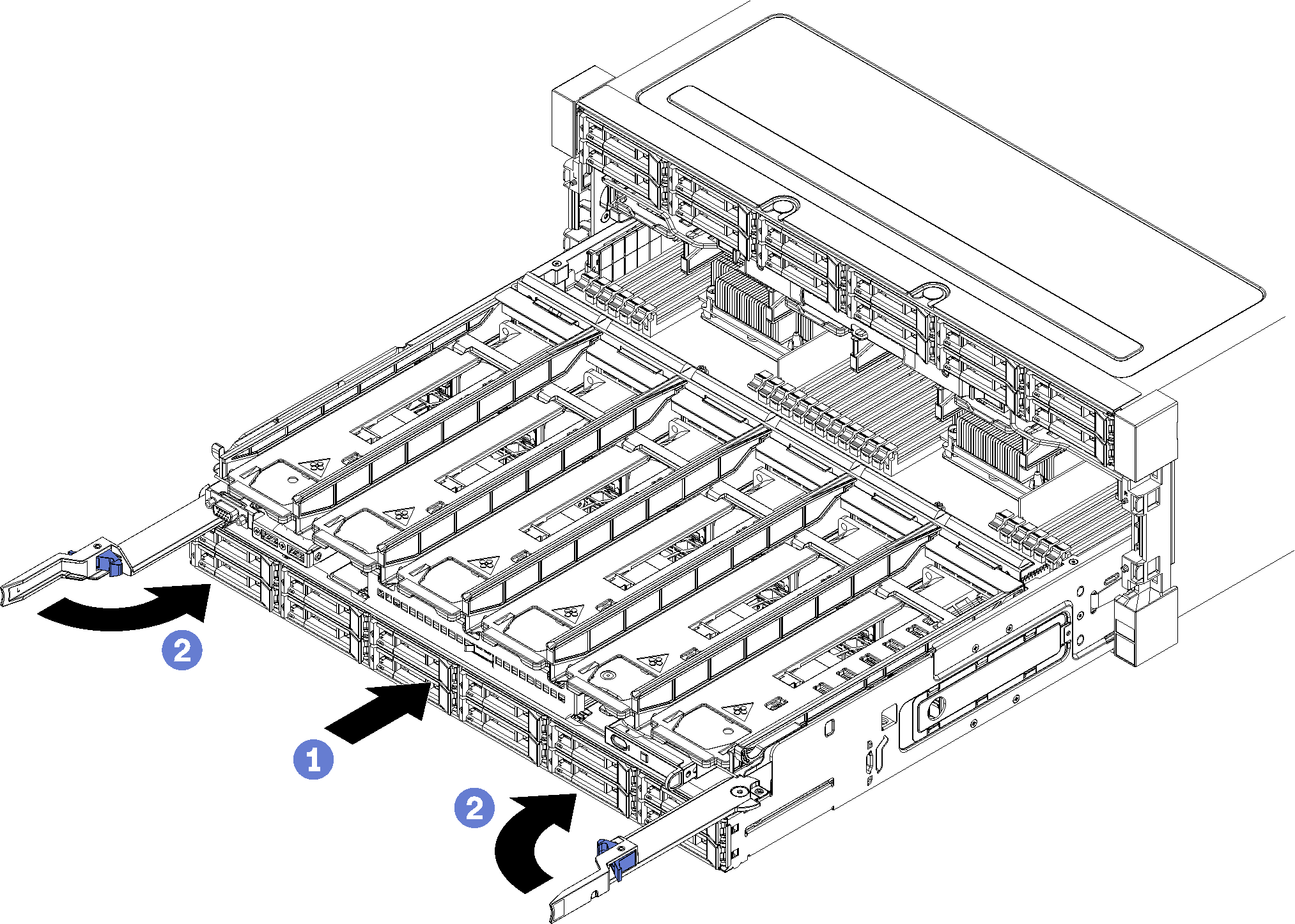
    Complete the following steps to remove the upper tray filler and install a compute tray:

    1. Remove the four screws (two each side) securing the upper tray filler.

      Upper tray filler removal
    2. Slide the upper tray filler out from the front of the server.
    3. Some cables may be packaged separately with the option, make sure all the cables are connected correctly to the lower system board and upper system board in the compute tray.
    4. Align the compute tray with the opening in the front of the chassis, and insert it.
    5. Fully open the compute tray release levers, and push the compute tray into the chassis until it stops.
    6. Rotate the compute tray release levers towards the center until they lock and are fully closed.

      Install the compute tray
    7. Remove the fan fillers in fan bay 7 to 12, and install fans in those bays.
  9. If a storage tray is installed in the upper-tray position, you must convert it to a compute tray to take advantage of eight processors.
    Note
    Cables that connect to the storage tray are longer than the cables that connect to the compute tray. For optimal cable routing, you should replace the following cables when converting from a storage tray to a compute tray in the upper-tray position:
    • Fan cage cable. Replace part number 01GW929 with part number 01GW928.

    • Drive power cable. Replace part number 01GW930 with part number 01GW917.

    • Drive Signal cable. Replace part number 01GW931 with part number 01GW918.

    Complete the following steps to convert a storage tray to a compute tray:

    1. Remove the upper tray from the server if you have not already done so.
    2. Disconnect all cables from the storage boards.
    3. Remove the storage board assembly.
    4. Install the system board into the lower bay in the tray.
    5. Connect cables to the lower system board.
    6. Install the system board into the upper bay in the tray.
    7. Connect cables to the upper system board.
    8. Remove the fan fillers in fan bay 8, 10, and 12, and install fans in those bays.
  10. Install the server back into a rack.

    See the ThinkSystem SR950 Rack Installation Instructions, which is available here:

    Resources and downloads

  11. Install all the compute tray and I/O tray that were removed.
  12. Install the front cover. See Install the front cover.

After installation is complete, reconnect all external cables and power on the server.