
Cable routing for common components

Use this section to understand how to route cables for common server components.

Cable routing for common components is different for the lower and upper trays:

Note
  • Make sure that all the cables go through the cable guides, as shown in the illustrations. See Cable guides for cable guide locations and descriptions.

  • Some cable connectors have locks or latches that must be disengaged to disconnect the cable.

Common cable routing (lower tray)

The following illustration shows cable routing for common components in the lower tray.
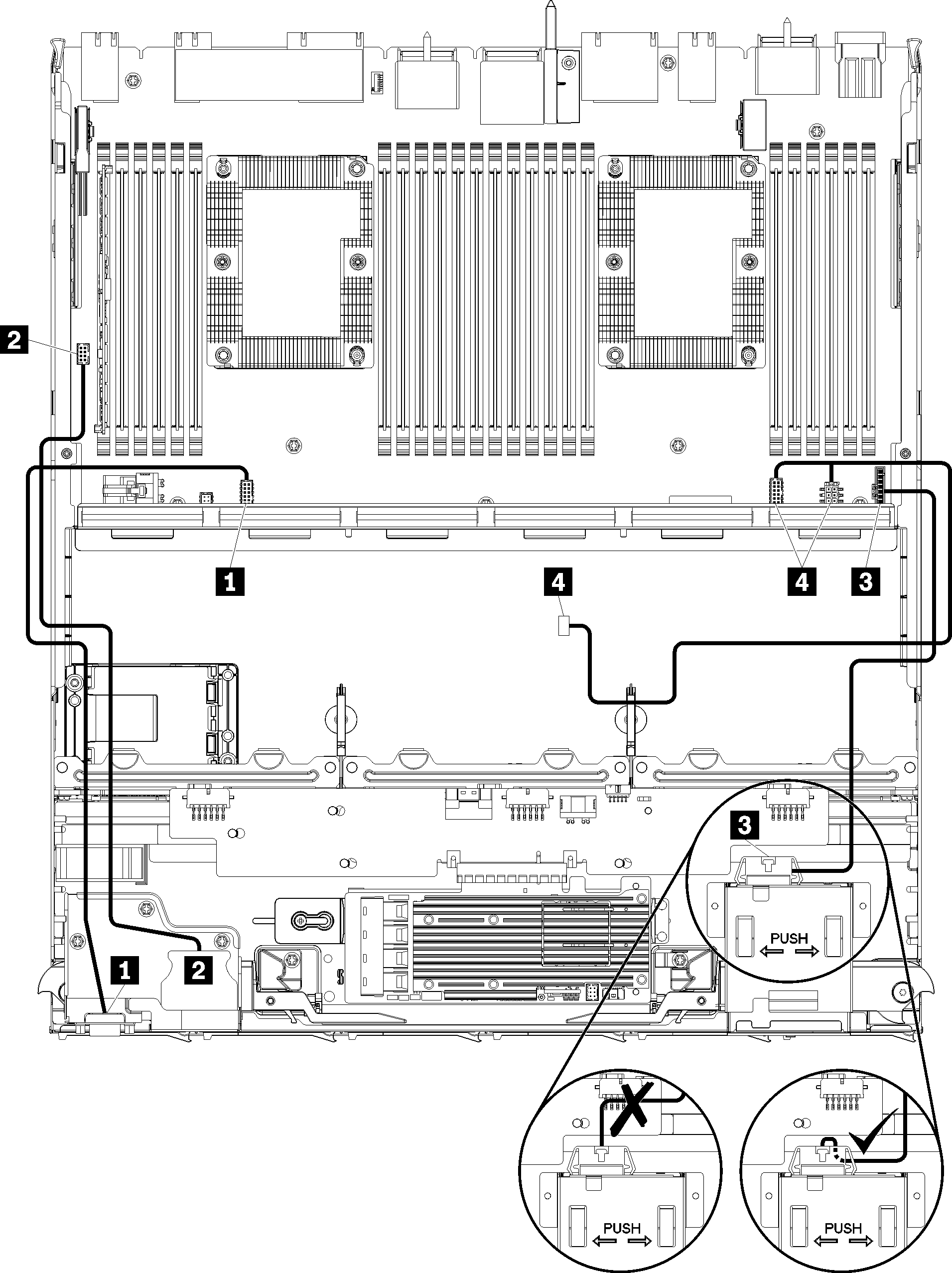
Figure 1. Cable routing, common cables (lower tray)

Table 1. Cable routing, common cables (lower tray)
CableRouting
1 Front panel video port
  • From: Front panel video port
  • To: Lower system board in lower compute tray, Front video connector (see System-board connectors)
2 Front panel USB ports
3 Control panel cable
  • From: Control panel connector
  • To: Lower system board in lower compute tray, Front panel connector (see System-board connectors)
Attention
Make sure the operator panel cable is folded beneath the connector, as shown in Cable routing, common cables (lower tray) to prevent the cable from pinching when the compute tray is fully assembled.
4 Fan cage cable
  • From: Fan cage connector (underside of fan cage)
  • To: Lower system board in lower compute tray, Fan board power (J56) and signal (J40) connectors (see System-board connectors)

Common cable routing (upper tray)

The following illustration shows cable routing for common components in the upper tray.
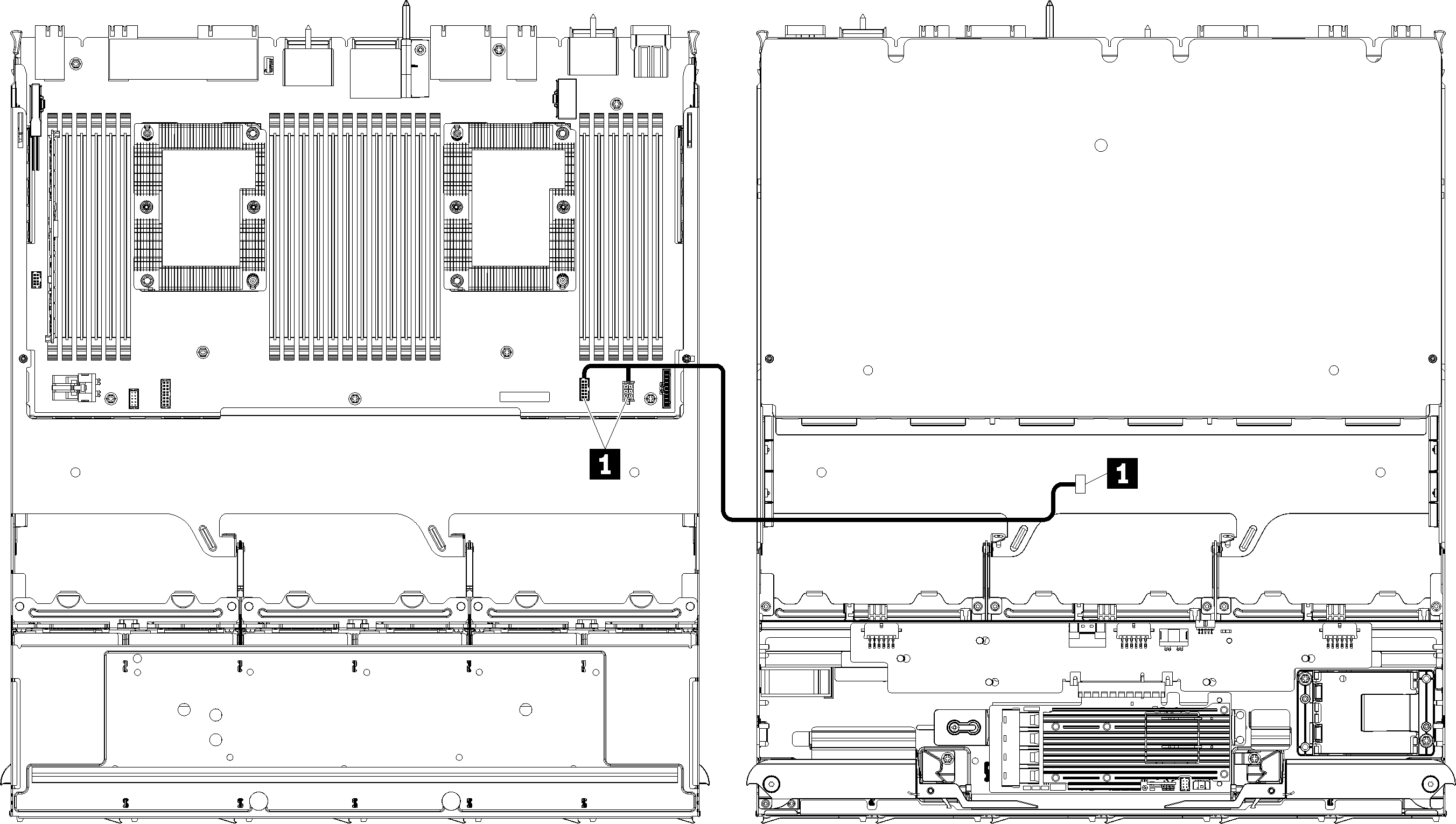
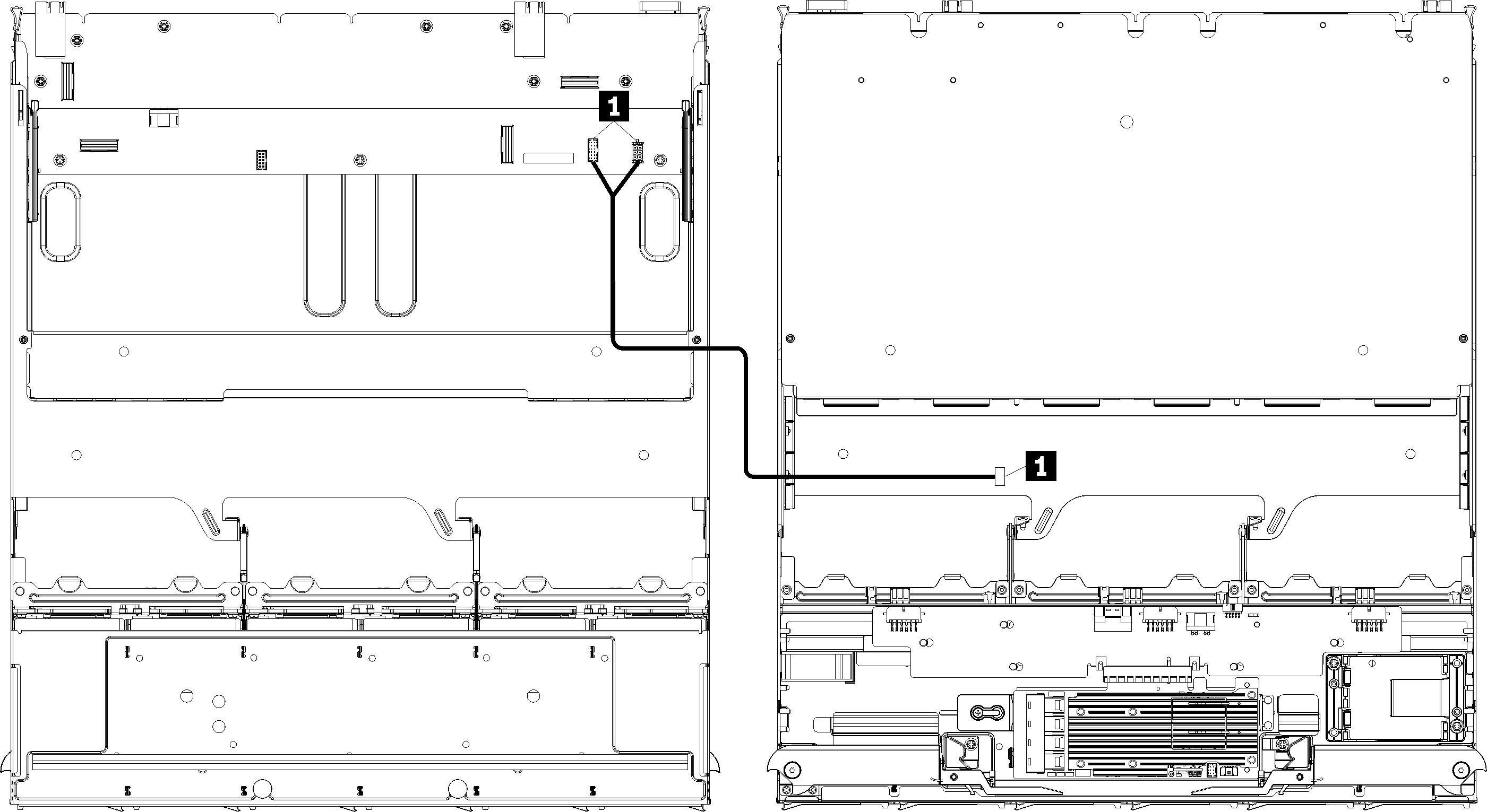
Figure 2. Cable routing, common cables (upper tray with system board)

Note
In this illustration, the image on the left shows the tray right-side up and the image on the right shows the tray upside down.
Figure 3. Cable routing, common cables (upper tray with storage-board assembly)

Note
In this illustration, the image on the left shows the tray right-side up and the image on the right shows the tray upside down.
Table 2. Cable routing, common cables (upper tray)
CableRouting
1 Fan cage cable
  • From: Fan cage connector (underside of fan cage)
  • To:
Note
Do not route the fan cage cable in the upper tray through any cable guides.