Front view
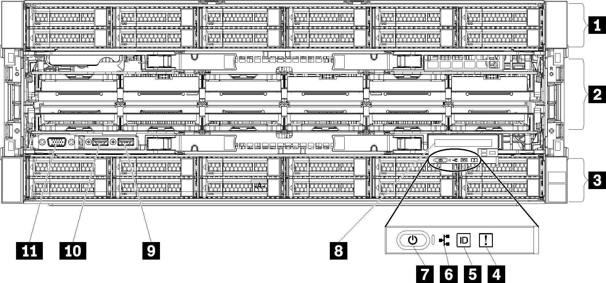
The front view of the server varies slightly by the model. In some models, components are replaced by fillers.
Front view of server
| Callout | Callout |
|---|---|
| 1 2.5-inch-drive bays (12-23) (on some models) | 7 Power button and power LED |
| 2 Fan slots (1-12) | 8 Front operator panel with pull-out LCD display |
| 3 2.5-inch-drive bays (0-11) | 9 USB 2.0 port |
| 4 System-error LED | 10 USB 2.0 Lenovo XClarity Controller management port |
| 5 System ID button/LED | 11 VGA Video port |
| 6 Network activity LED |
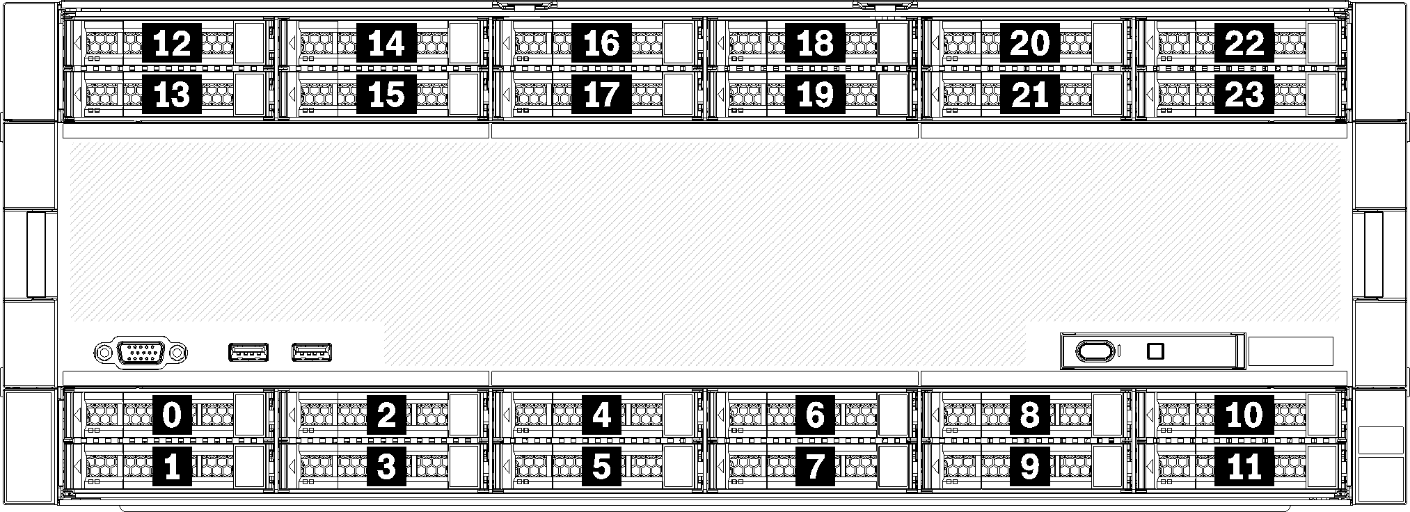
1 2.5-inch-drive bays (12-23) (on some models)
The drive bays are used to install 2.5-inch drives. When you install drives, follow the order of the drive bay numbers. The EMI integrity and cooling of the server are protected by having all drive bays occupied. The vacant drive bays must be occupied by drive bay fillers or drive fillers.
2 Fan slots (1-12)
Install fans to these slots.
3 2.5-inch-drive bays (0-11)
The drive bays are used to install 2.5-inch drives. When you install drives, follow the order of the drive bay numbers. The EMI integrity and cooling of the server are protected by having all drive bays occupied. The vacant drive bays must be occupied by drive bay fillers or drive fillers.
4 System-error LED
For information about the system-error LED, see Front operator panel.
5 System ID button/LED
For information about the system ID button/LED, see Front operator panel.
6 Network activity LED
For information about the network activity LED, see Front operator panel.
7 Power button and power LED
For information about the power button and power LED, see Front operator panel.
8 Front operator panel with pull-out LCD display
For information about the front operator panel with pull-out LCD display, see LCD system information display panel.
9 USB 2.0 port
Connect a USB device, such as a mouse, keyboard, or other devices, to either of these connectors.
10 USB 2.0 Lenovo XClarity Controller management port
Connection to XClarity Controller is primarily intended for users with a mobile device running the XClarity Controller mobile application. When a mobile device is connected to this USB port, an Ethernet over USB connection is established between the mobile application running on the device and the XClarity Controller.
Select Network in BMC Configuration to view or modify settings.
Four types of settings are available:
Host only mode
In this mode, the USB port is always solely connected to the server.
BMC only mode
In this mode, the USB port is always solely connected to XClarity Controller.
Shared mode: owned by BMC
In this mode, connection to the USB port is shared by the server and XClarity Controller, while the port is switched to XClarity Controller.
Shared mode: owned by host
In this mode, connection to the USB port is shared by the server and XClarity Controller, while the port is switched to the server.
11 VGA Video port
- When the optional front VGA connector is in use, the rear one will be disabled.
- The maximum video resolution is 1920 x 1200 at 60 Hz.
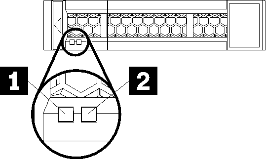
Drive LEDs
| Callout | Callout |
|---|---|
| 1 Drive activity LED (green) | 2 Drive status LED (yellow) |
1 Drive activity LED (green):
Each hot-swap drive comes with an activity LED. If the LED is lit, it indicates that the drive is powered, but not actively reading or writing data. If the LED is flashing, the drive is being accessed.
2 Drive status LED (yellow):
These LEDs are on SAS or SATA hard disk drives and solid-state drives. When one of these LEDs is lit, it indicates that the drive has failed. When this LED is flashing slowly (one flash per second), it indicates that the drive is being rebuilt. When the LED is flashing rapidly (three flashes per second), it indicates that the controller is identifying the drive.