Rear view
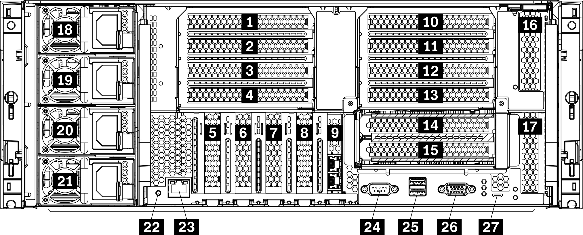
The rear of the server provides access to several components, including the power supplies, PCIe adapters, serial port, and Ethernet ports.
| Callout | Callout |
|---|---|
| 1 PCIe slot 1 (on riser 1) | 15 PCIe slot 15 (on riser 2) for ML2 x16 network adapter |
| 2 PCIe slot 2 (on riser 1) | 16 PCIe slot 16 (on riser 3) |
| 3 PCIe slot 3 (on riser 1) | 17 PCIe slot 17 (on riser 3) |
| 4 PCIe slot 4 (on riser 1) | 18 Power supply 4 (optional) |
| 5 PCIe slot 5 | 19 Power supply 3 (optional) |
| 6 PCIe slot 6 | 20 Power supply 2 (optional) |
| 7 PCIe slot 7 | 21 Power supply 1 |
| 8 ML2 x16 network adapter slot | 22 NMI button |
| 9 LOM adapter slot | 23 XClarity Controller network connector (RJ45) |
| 10 PCIe slot 10 (on riser 2) | 24 Serial connector |
| 11 PCIe slot 11 (on riser 2) | 25 USB 3.0 connectors (2) |
| 12 PCIe slot 12 (on riser 2) | 26 VGA video port |
| 13 PCIe slot 13 (on riser 2) | 27 Service only connector |
| 14 PCIe slot 14 (on riser 2) |
slotsare assigned to components elsewhere in the server:
PCIe slot 18 is assigned to the RAID card in the lower tray.
PCIe slot 19 is assigned to the RAID card in the upper tray.
PCIe slot 20 is assigned to the M.2 backplane inside the I/O tray.
1 2 3 4 PCIe slot 1-4 (on riser 1)
Install PCIe adapters into these slots.
5 6 7 PCIe slot 5-7
Install PCIe adapters into these slots.
8 ML2 x16 network adapter slot
Install ML2 x16 network adapter into this slot.
9 LOM adapter slot
Install LOM adapter into this slot.
10 11 12 13 14 15 PCIe slot 10-15 (on riser 2)
16 17 PCIe slot 16-17 (on riser 3)
Install PCIe adapters into these slots.
18 19 20 21 Power supply 1-4
The hot-swap redundant power supplies help you avoid significant interruption to the operation of the system when a power supply or an input power source fails. A failed power supply can be replaced without turning off the server. You can purchase a power supply option from Lenovo and install the power supply to provide power redundancy or additional power capacity without turning off the server.
For information about minimum power supply requirements and power redundancy, see Install a power supply.
Each hot-swap power supply has three status LEDs. See Rear view LEDs for information.
22 NMI button
Press this button to force a nonmaskable interrupt to the processor. You might have to use a pen or the end of a straightened paper clip to press the button. You can also use it to force a blue-screen memory dump. Use this button only when you are directed to do so by Lenovo Support.
23 XClarity Controller network connector (RJ45)
Used to attach an Ethernet cable to manage the system using XClarity Controller.
24 Serial connector
Connect a 9-pin serial device to this connector. The serial port is shared with the XCC. The XCC can take control of the shared serial port to redirect serial traffic, using Serial over LAN (SOL).
25 USB 3.0 connectors (2)
Used to attach a device that requires a USB 2.0 or USB 3.0 connection, such as a keyboard, a mouse, or a USB flash drive.
26 VGA video port
Used to attach a VGA-compatible video device, such as a VGA monitor.
27 Service only connector
This connector is reserved for service only.