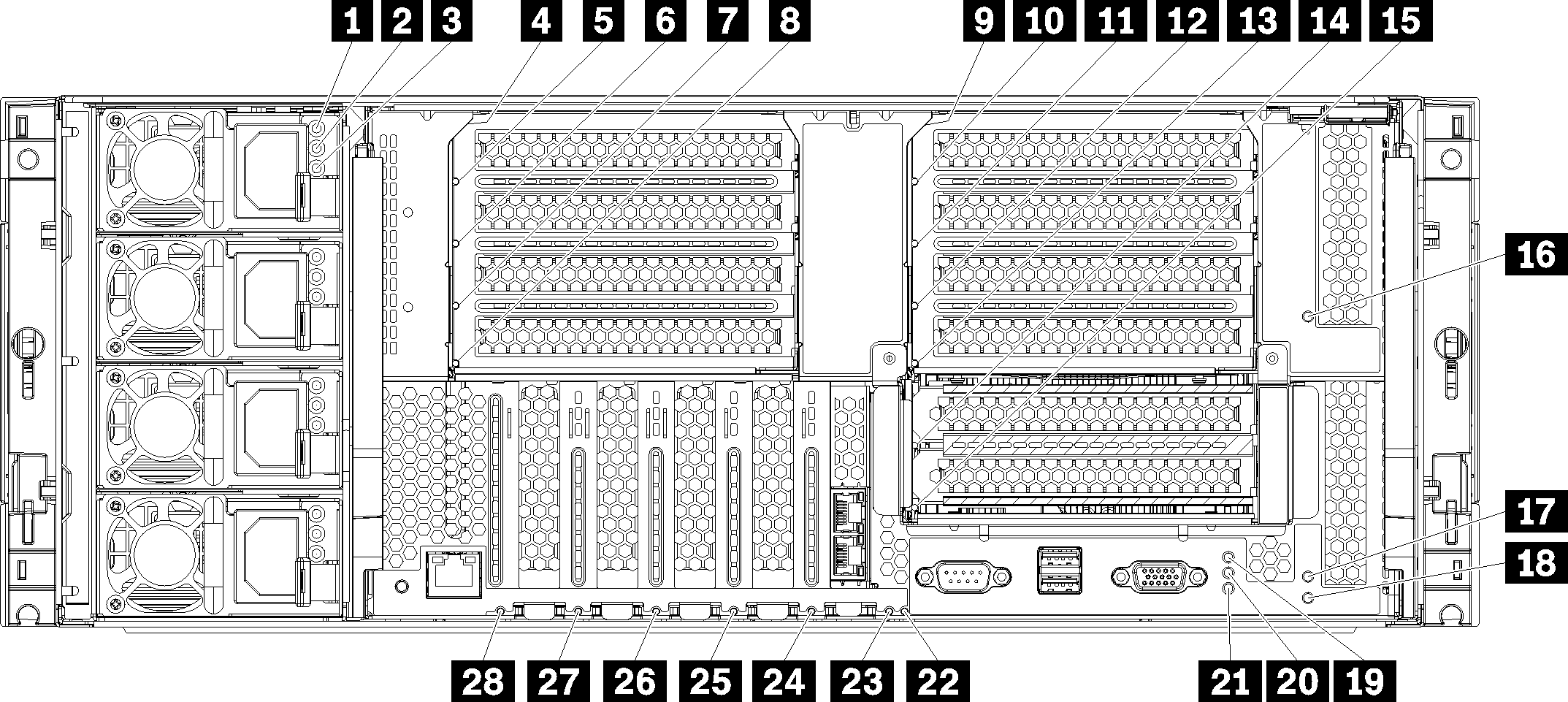
Rear view LEDs
The illustration in this section shows the LEDs on the rear the server.
| LED | Description |
|---|---|
| 1 Input status (AC) (green) | The input status LED can be in one of the following states:
|
| 2 Output status (DC) (green) | The output status LED can be in one of the following states:
|
| 3 Fault LED (yellow) |
|
| LED | Description |
|---|---|
| 19 Power LED (green) | The states of the power LED are as follows:
|
| 20 System ID LED (blue) | Use this blue LED to visually locate the server among other servers. You can use Lenovo XClarity Administrator to light this LED remotely. |
| 21 System error LED (yellow) | When this yellow LED is lit, it indicates that a system error has occurred. A system-error LED is also on the front operator information panel. Messages on the LCD system information display panel and LEDs on other server components might also be lit to help isolate the error. This LED is controlled by the Lenovo XClarity Controller. |
| Callout | Callout |
|---|---|
| 4 Riser 1 to 4 fault LED | 15 Adapter 15 fault LED |
| 5 Adapter 1 fault LED | 16 Adapter 16 fault LED |
| 6 Adapter 2 fault LED | 17 Adapter 17 fault LED |
| 7 Adapter 3 fault LED | 18 Riser 16 through 17 fault LED |
| 8 Adapter 4 fault LED | 22 3v fault (system battery) LED |
| 9 Riser 10 to 15 fault LED | 23 I/O-board fault LED |
| 10 Adapter 10 fault LED | 24 LOM adapter fault LED |
| 11 Adapter 11 fault LED | 25 ML2 x16 network adapter fault LED |
| 12 Adapter 12 fault LED | 26 Adapter 7 fault LED |
| 13 Adapter 13 fault LED | 27 Adapter 6 fault LED |
| 14 Adapter 14 fault LED | 28 Adapter 5 fault LED |