Front operator panel
The following illustration shows the controls and LEDs on the front operator panel.
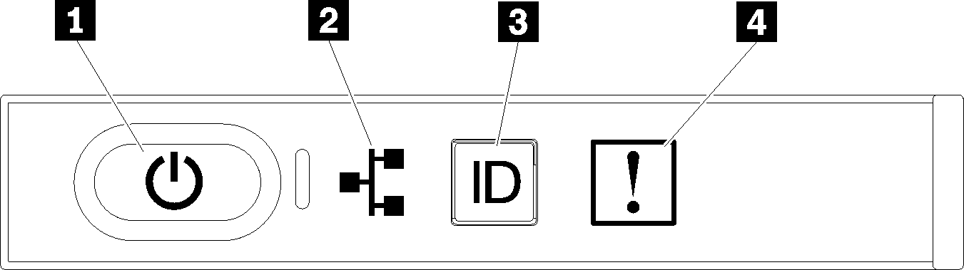
| Callout | Callout |
|---|---|
| 1 Power button and power LED | 3 System ID button/LED |
| 2 Network activity LED | 4 System-error LED |
1 Power button and power LED: Press this button to turn the server on and off manually. The states of the power LED are as follows:
- Off: Power is not present or the power supply has failed.
- Flashing rapidly (4 times per second): The server is turned off and is not ready to be turned on. The power button is disabled. This will last approximately 5 to 10 seconds.
- Flashing slowly (once per second): The server is turned off and is ready to be turned on. You can press the power button to turn on the server.
- On: The server is turned on.
2 Network activity LED: When this LED flickers, it indicates that the server is transmitting to or receiving signals from the Ethernet LAN.
3 System ID button/LED: Use this blue LED to visually locate the server among other servers. This LED is also used as a presence detection button. You can use Lenovo XClarity Administrator to light this LED remotely.
4 System-error LED: When this yellow LED is lit, it indicates that a system error has occurred. A system-error LED is also on the rear of the server. Messages on the LCD system information display panel and LEDs on other server components might also be lit to help isolate the error. This LED is controlled by the Lenovo XClarity Controller.
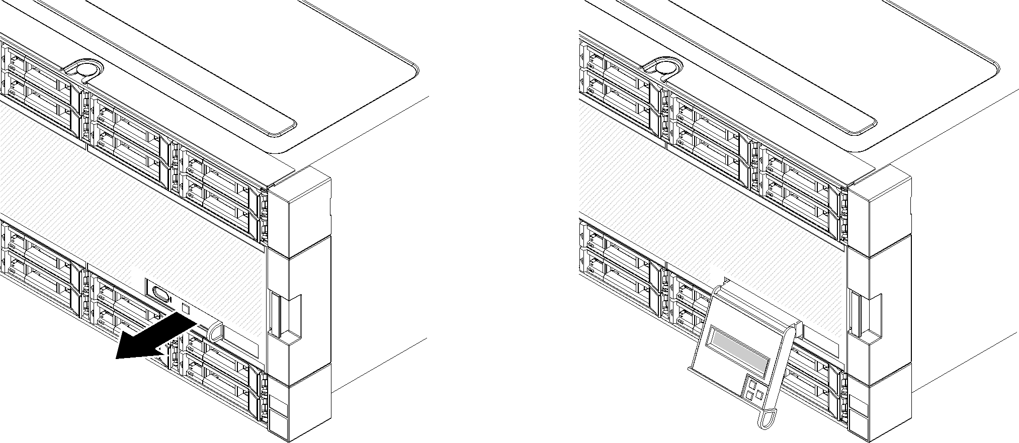
LCD system information display panel
The front operator panel comes with a tab, which can be pulled to access the LCD system information display panel. See LCD system information display panel for more information.