Use this section to understand how to route cables for drives and related components.
Cable routing for drive components is different for the lower and upper trays:
Make sure that all the cables go through the cable guides, as shown in the illustrations. See Cable guides for cable guide locations and descriptions.
Some cable connectors have locks or latches that must be disengaged to disconnect the cable.
The RAID cards in the illustration might be different than the RAID card in your system. Connector locations for all RAID cards are similar.
Cable routing for drive components is different for SAS and NVMe drives:
Common drive cables (lower tray)
Common drive cables are used by both SAS and NVMe drives.
Figure 1. Cable routing, common drive cables (lower tray)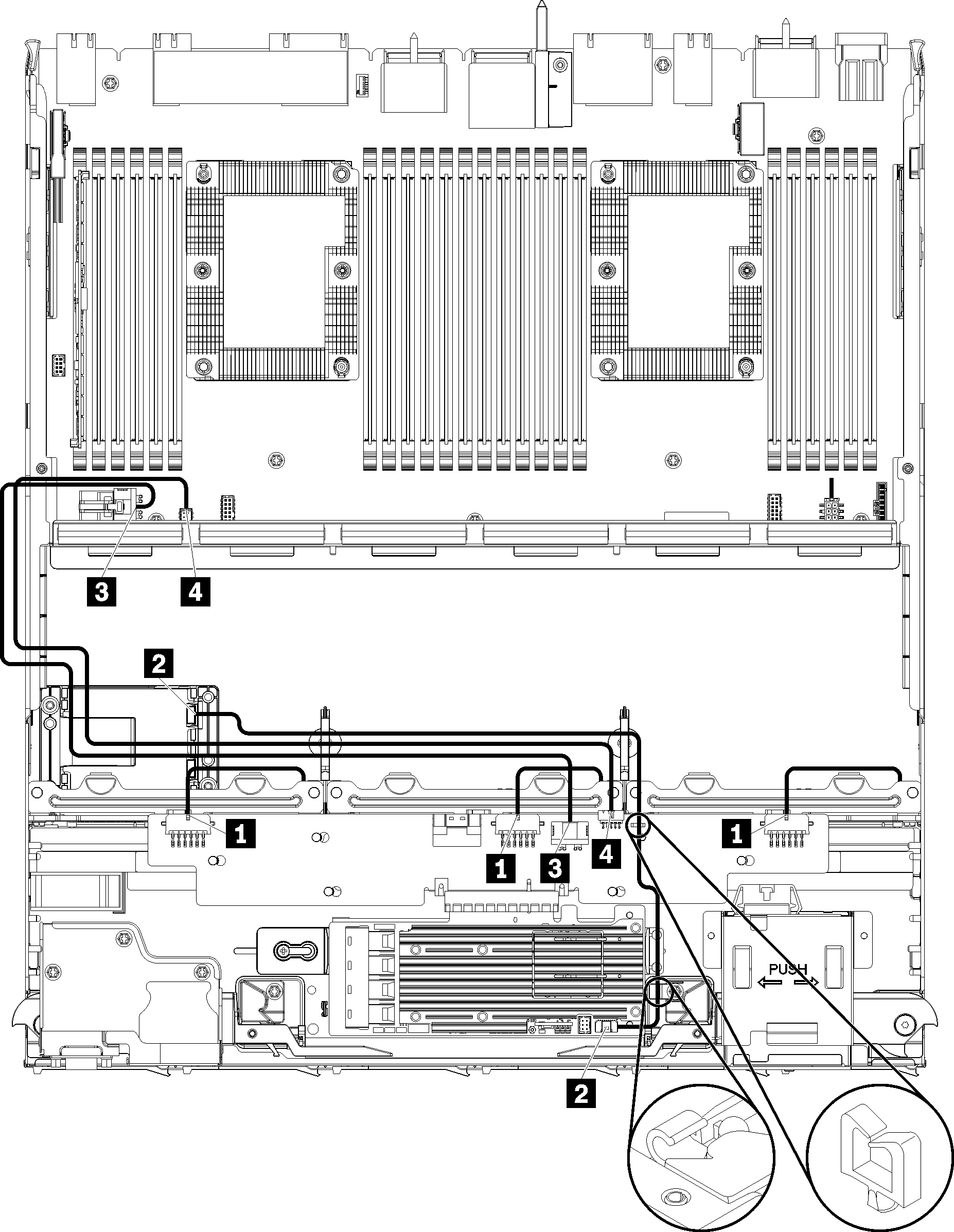
Table 1. Cable routing, common drive cables (lower tray)| Cable | Routing |
|---|
| 1 Power to drive backplanes 1, 2, and 3 | - From: Storage interposer (see Storage interposer connectors)
For drive backplane 1, use interposer BP 1/6 connector For drive backplane 2, use interposer BP 2/5 connector For drive backplane 3, use interposer BP 3/4 connector
- To: Drive backplane,
Power connector (see Drive backplane connectors)
|
| 2 RAID flash power module | - From: RAID flash power module connector
- To: RAID card, flash power module connector
|
| 3 Drive power | |
| 4 Drive signal | |
SAS drive cables (lower tray)
Common drive cables are used by only SAS drives.
Figure 2. Cable routing, SAS drive cables (lower tray)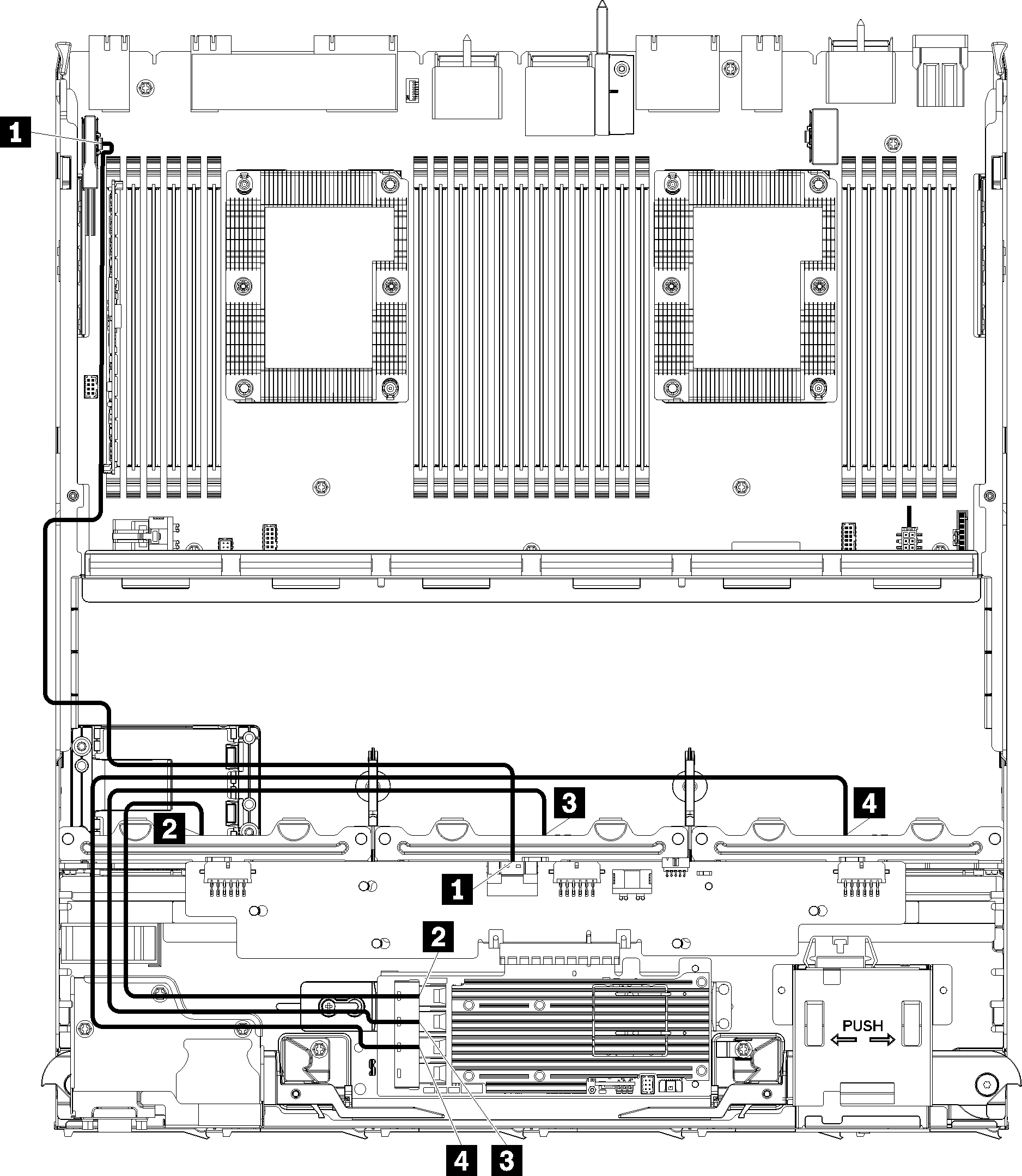
Table 2. Cable routing, SAS drive cables (lower tray)| Cable | Gen 3 RAID routing | Gen 4 RAID routing |
|---|
| 1 PCIe SAS interface | |
| 2 RAID interface for drive backplane 1 | | |
| 3 RAID interface for drive backplane 2 | | |
| 4 RAID interface for drive backplane 3 | |
NVMe drive cables (lower tray)
Common drive cables are used by only NVMe drives.
Figure 3. Cable routing, NVMe drive cables (lower tray)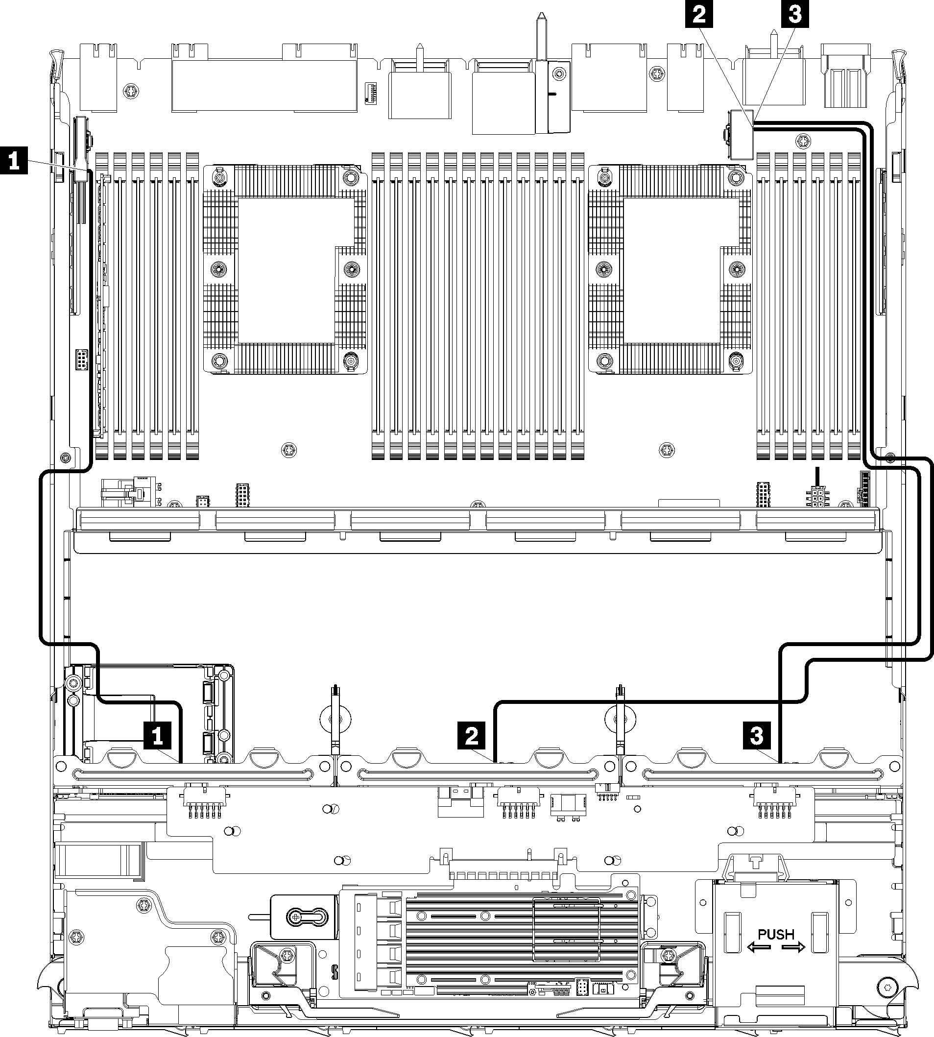
Table 3. Cable routing, NVMe drive cables (lower tray)| Cable | Routing |
|---|
| 1 Drive backplane 1 NVMe | |
| 2 Drive backplane 2 NVMe | |
| 3 Drive backplane 3 NVMe | |
Cable routing for drive components is different for SAS and NVMe drives:
Common drive cables (upper tray)
Common drive cables are used by both SAS and NVMe drives.
Figure 4. Cable routing, common drive cables (upper tray with compute system board)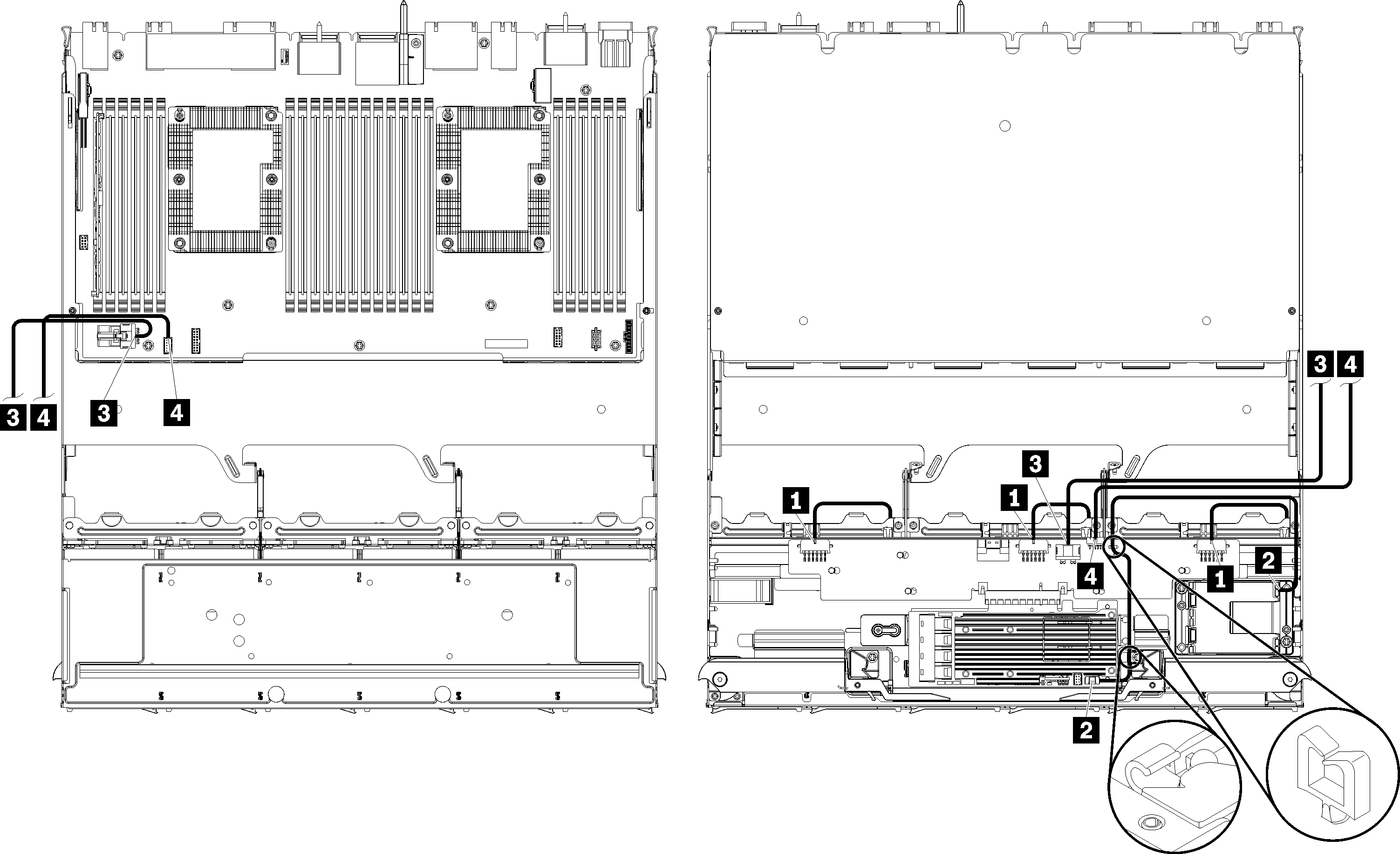
In this illustration, the image on the left shows the tray right-side up and the image on the right shows the tray upside down.
Figure 5. Cable routing, common drive cables (upper tray with storage-board assembly)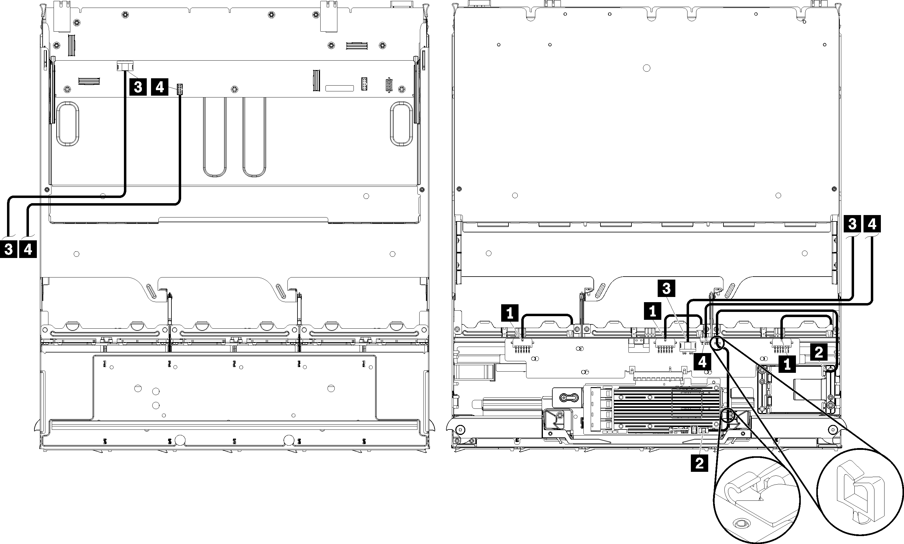
In this illustration, the image on the left shows the tray right-side up and the image on the right shows the tray upside down.
Table 4. Cable routing, common drive cables (upper tray)| Cable | Routing |
|---|
| 1 Power to drive backplanes 4, 5, and 6 | - From: Storage interposer (see Storage interposer connectors)
For drive backplane 4, use interposer BP 3/4 connector For drive backplane 5, use interposer BP 2/5 connector For drive backplane 6, use interposer BP 1/6 connector
- To: Drive backplane, connector
Power (see Drive backplane connectors)
|
| 2 RAID flash power module | - From: RAID flash power module connector
- To: RAID card, flash power module connector
|
| 3 Drive power | |
| 4 Drive signal | |
SAS drive cables (upper tray)
Common drive cables are used by only SAS drives.
Figure 6. Cable routing, SAS drive cables (upper tray with system board)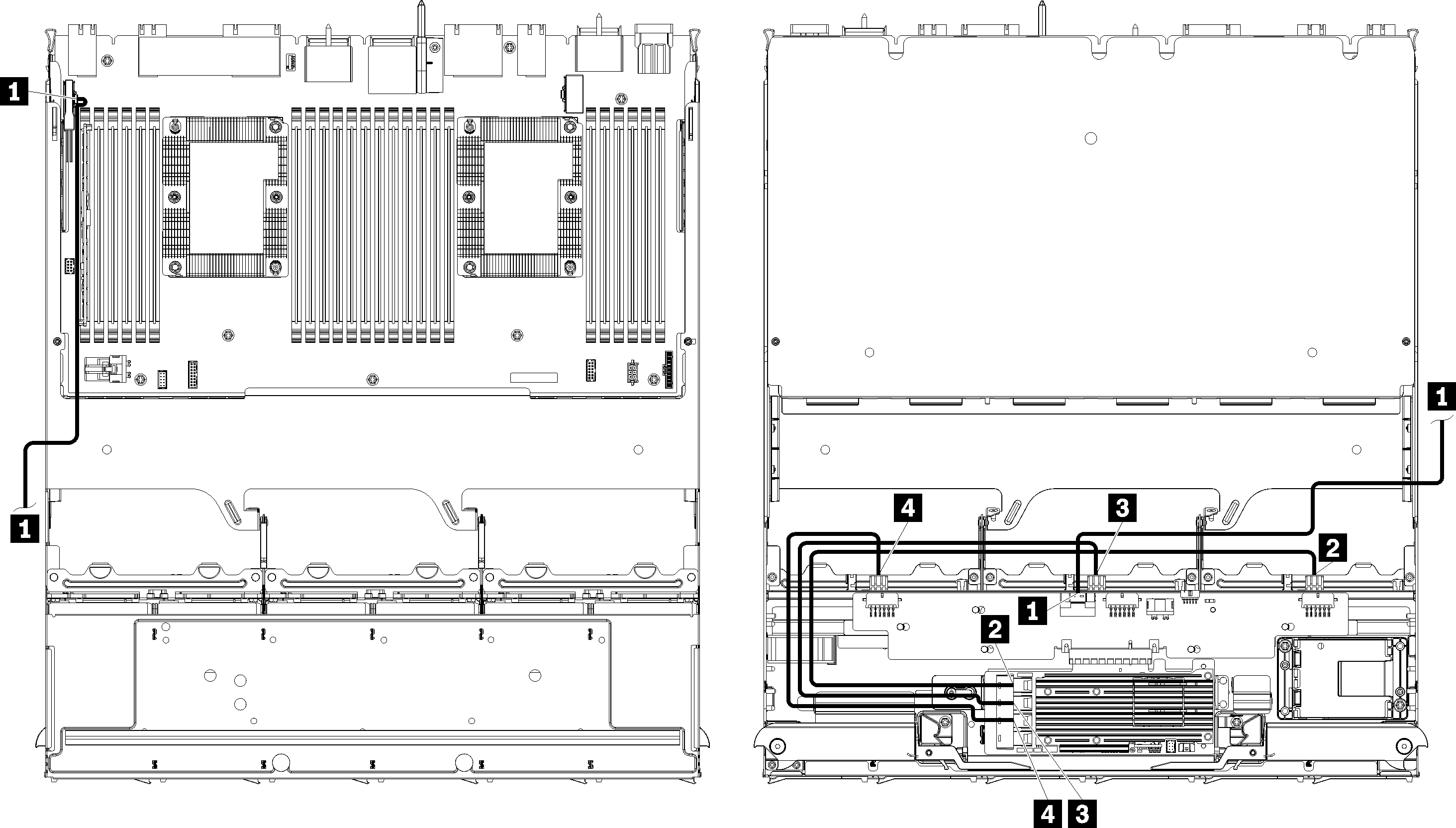
In this illustration, the image on the left shows the tray right-side up and the image on the right shows the tray upside down.
Figure 7. Cable routing, SAS drive cables (upper tray with storage-board assembly)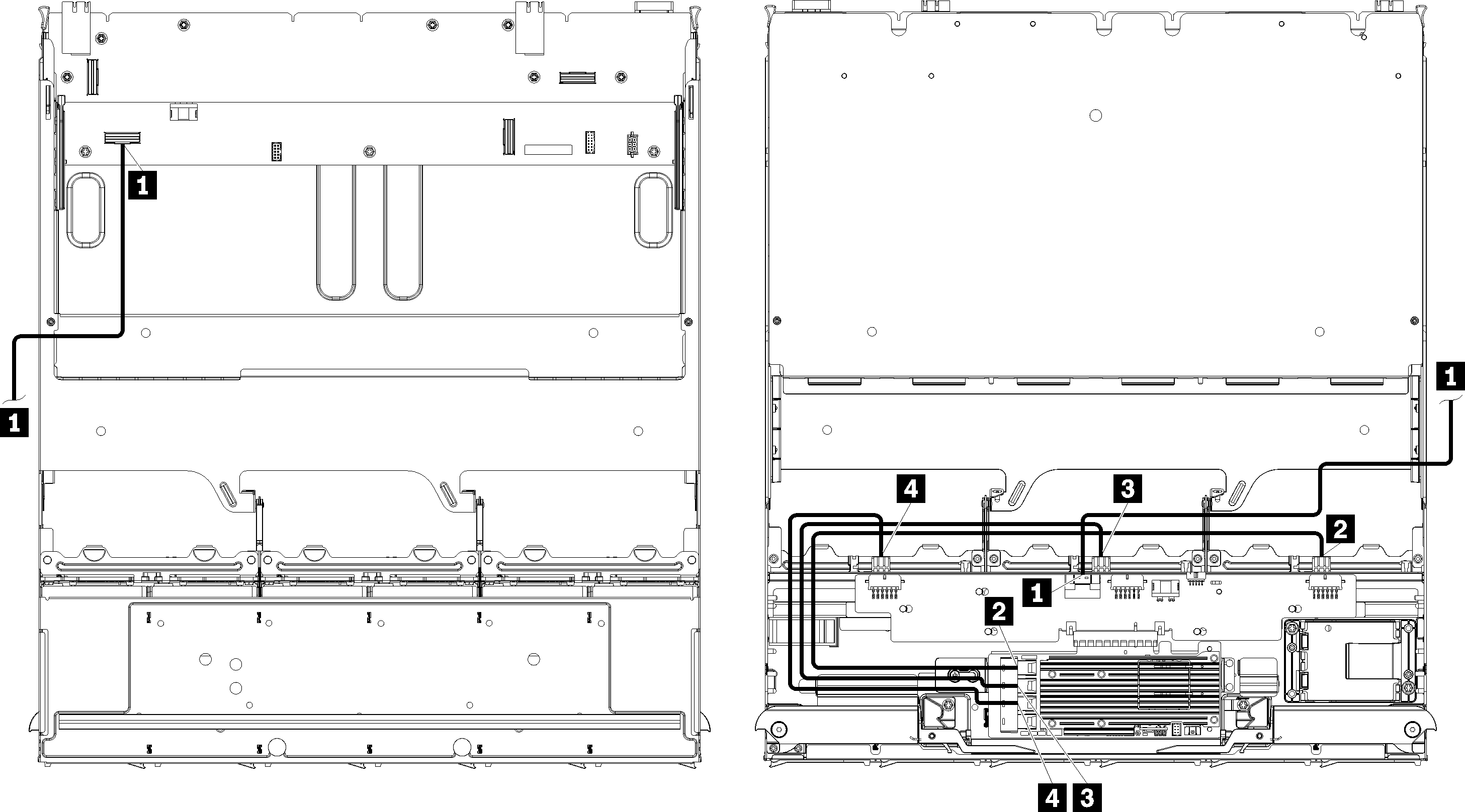
In this illustration, the image on the left shows the tray right-side up and the image on the right shows the tray upside down.
Table 5. Cable routing, SAS drive cables (upper tray)| Cable | Gen 3 RAID routing | Gen 4 RAID routing |
|---|
| 1 PCIe SAS interface | |
| 2 RAID interface for drive backplane 4 | | |
| 3 RAID interface for drive backplane 5 | |
| 4 RAID interface for drive backplane 6 | | |
NVMe drive cables (upper tray)
Common drive cables are used by only NVMe drives.
Figure 8. Cable routing, NVMe drive cables (upper tray with system board)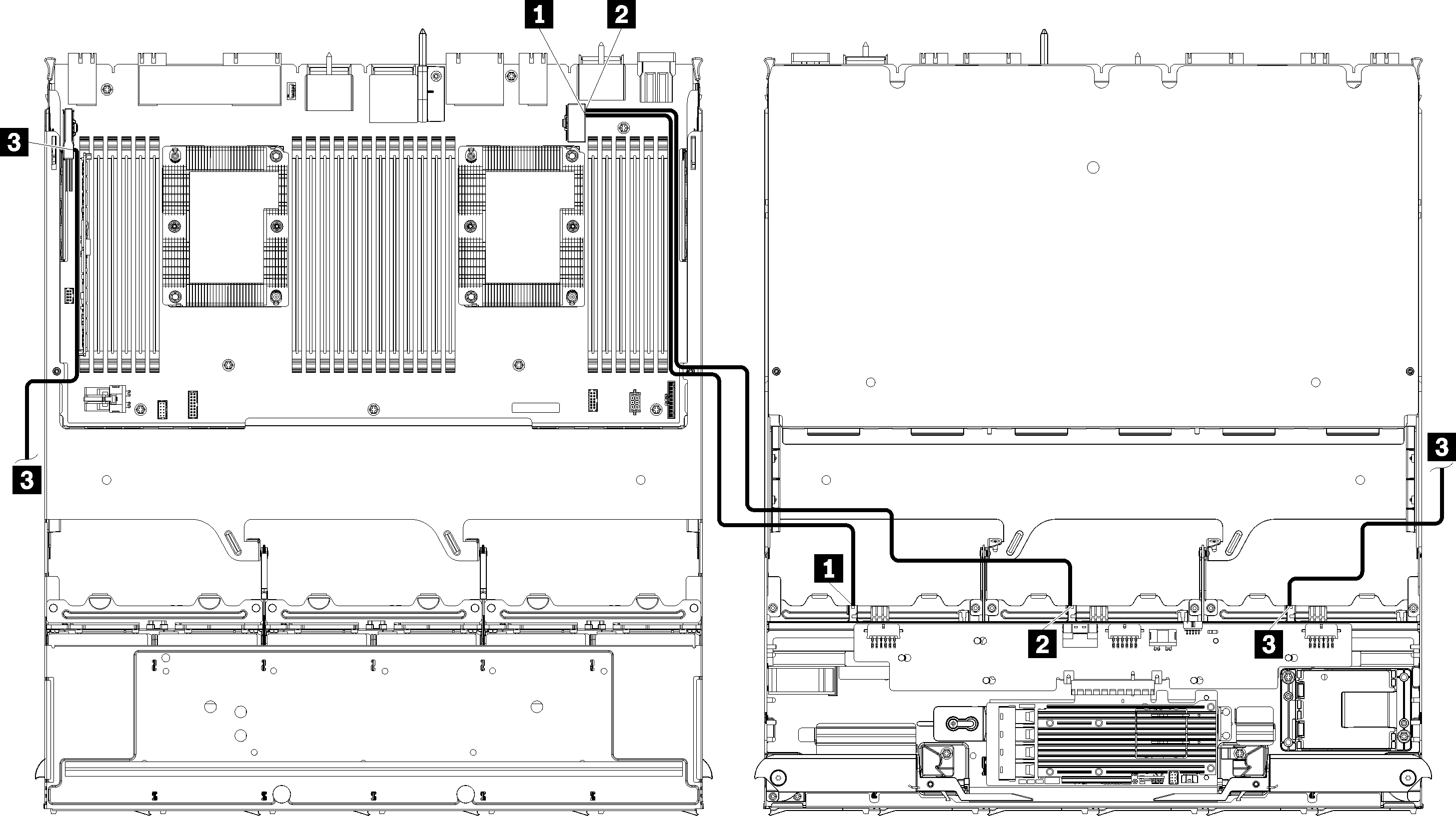
In this illustration, the image on the left shows the tray right-side up and the image on the right shows the tray upside down.
Figure 9. Cable routing, NVMe drive cables (upper tray with storage-board assembly)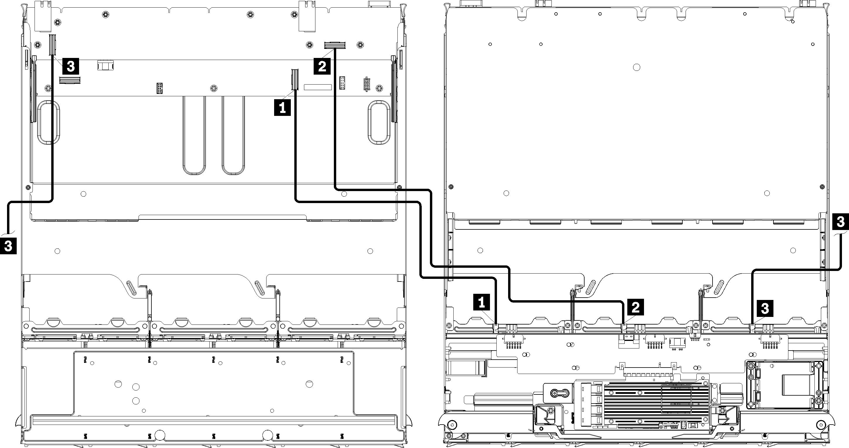
In this illustration, the image on the left shows the tray right-side up and the image on the right shows the tray upside down.
Table 6. Cable routing, NVMe drive cables (upper tray)| Cable | Routing |
|---|
| 1 Drive backplane 6 NVMe | |
| 2 Drive backplane 5 NVMe | |
| 3 Drive backplane 4 NVMe | |