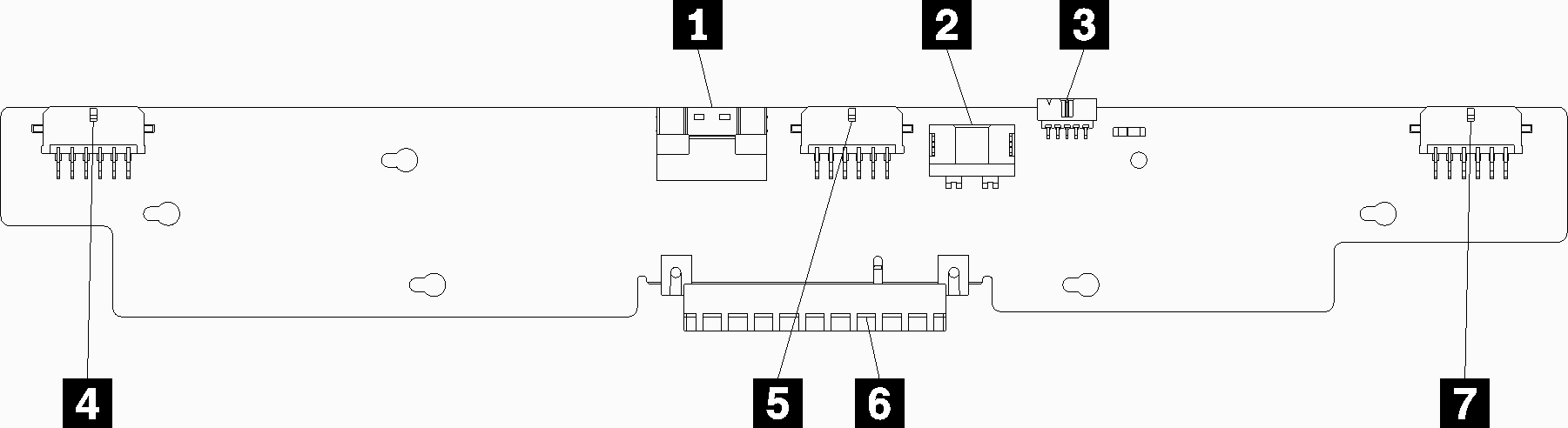
Storage interposer connectors
The following illustration shows the internal connectors on the interposer.
Note
Some cable connectors have locks or latches that must be disengaged to disconnect the cable.
For information about interposer cable routing, see Cable routing for drives.
Figure 1. Storage interposer connectors
| Callout | Callout |
|---|---|
| 1 PCIe SAS interface from system board (PCIE) (SAS only) | 5 Power for drive to backplane 2 or 5 (BP 2/5) |
| 2 Drive power from system board (POWER) | 6 PCI connector to RAID card |
| 3 Drive signal from system board (SIDEBAND) | 7 Power for drive to backplane 3 or 4 (BP 3/4) |
| 4 Power for drive to backplane 1 or 6 (BP 1/6) |
Give documentation feedback