I/O tray connectors
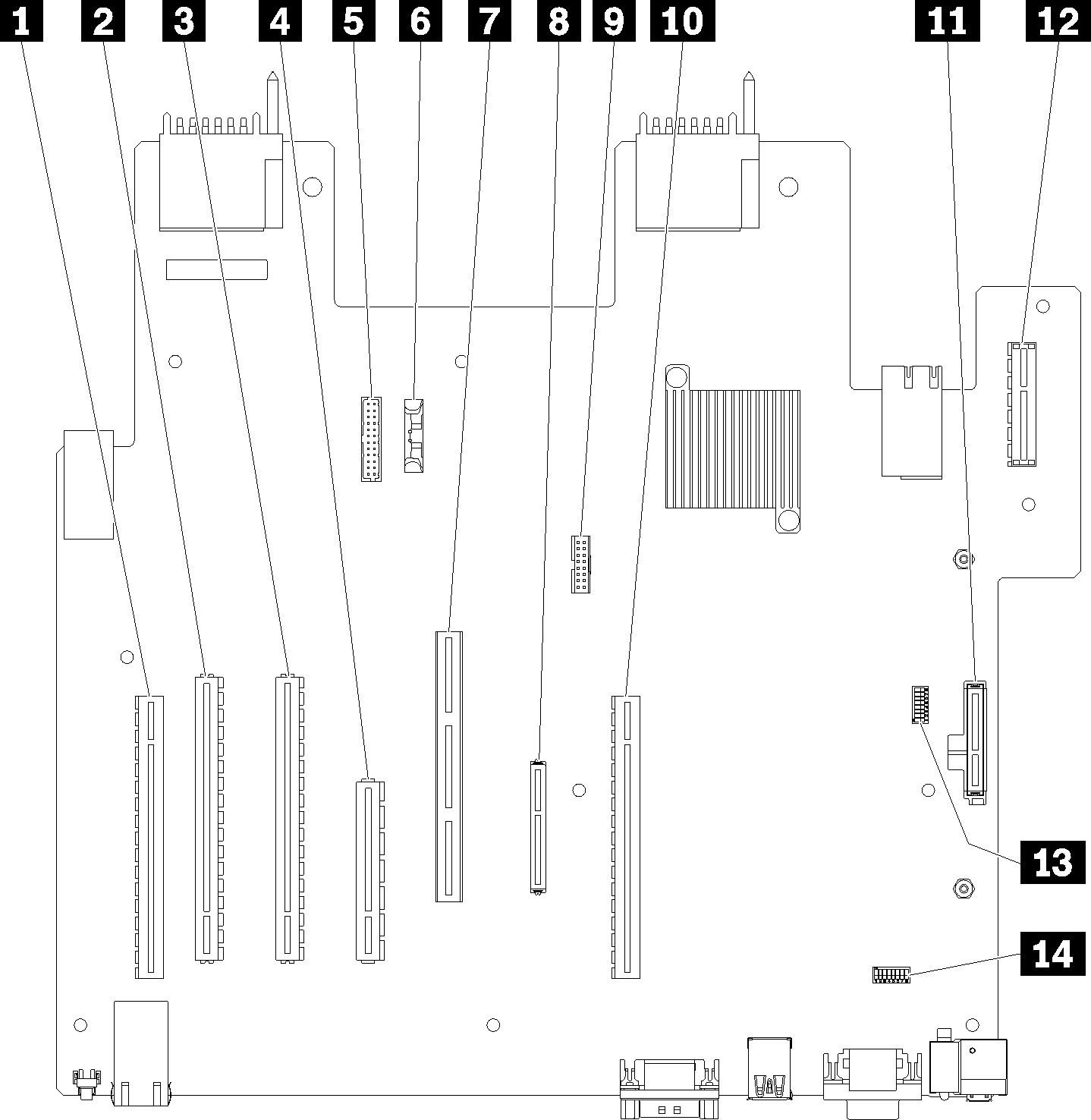
The following illustration shows the internal connectors on the I/O tray (including connectors of PCIe slot 5 to 8 and the LOM connector of slot 9).
For information about connectors on I/O tray risers, see I/O tray riser connectors. For information about all external connectors on the rear of the server, including those on the I/O tray, see Rear view.
Figure 1. I/O tray connectors
| Callout | Callout |
|---|---|
| 1 Riser for slot 1 to 4 connectors (Riser 1) | 8 Network (LOM) connector (slot 9) |
| 2 PCIe3, x16, 75 watt connector (slot 5) | 9 TCM connector (see Enable TPM/TCM) |
| 3 PCIe3, x16, 75 watt connector (slot 6) | 10 Riser for slot 10 to 15 connectors (Riser 2) |
| 4 PCIe3, x8, 25 watt connector (slot 7) | 11 M.2 SATA/PCIe (Hypervisor) backplane connector (see note following this table) |
| 5 Signal cable to power backplane | 12 Riser for PCIe slot 16 to 17 (Riser 3) |
| 6 Battery (CR2032) | 13 SW2 - Switch block 2 |
| 7 ML2 PCIe3, x16 connector (slot 8) | 14 SW1 - Switch block 1 Note This switch block is reserved. |
Note
The following PCIe
slotsare assigned to components elsewhere in the server:
PCIe slot 18 is assigned to the RAID card in the lower tray.
PCIe slot 19 is assigned to the RAID card in the upper tray.
PCIe slot 20 is assigned to the M.2 backplane inside the I/O tray.
Give documentation feedback