I/O tray switches
Two switch blocks are located on the I/O tray
SW1
The switch block SW1 is located near the VGA connector on the I/O tray. All switches in this switch block are reserved.
SW2
The switch block SW2 is located near the M2 SATA/PCIe backbplane connector.
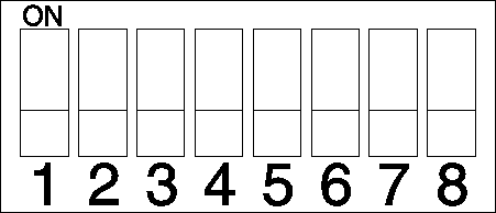
Table 1 describes the functions of the switch block.
| Switch number | Default position | Description |
|---|---|---|
| 1 | Off | TPM/TCM physical presence. |
| 2 | Off | Reserved. |
| 3 | Off | Reserved. |
| 4 | Off | Clear CMOS memory. When this switch is toggled to ON, it clears the data in CMOS memory, which clears the power-on password. |
| 5 | Off | Force UEFI recovery. Changing the position of the switch to ON will force the system to boot from the recovery UEFI image. |
| 6 | Off | Force XCC backup bank. Changing the position of the switch to ON will force the system to boot from the backup XCC bank. |
| 7 | Off | Power-on password override. Changing the position of this switch bypasses the power-on password check the next time the server is turned on and starts the Lenovo XClarity Provisioning Manager so that you can change or delete the power-on password. You do not have to move the switch back to the default position after the power-on password is overridden. Changing the position of this switch does not affect the administrator password check if an administrator password is set. |
| 8 | Off | Reserved |
Important
- Before you change any switch settings or move any jumpers, turn off the server; then, disconnect all power cords and external cables. Review the information in Safety Information page, Installation Guidelines, Handling static-sensitive devices, and Power off the server (disconnect input power).
Give documentation feedback