Memory module installation rules
Memory modules must be installed in a specific order based on the memory configuration of the server.
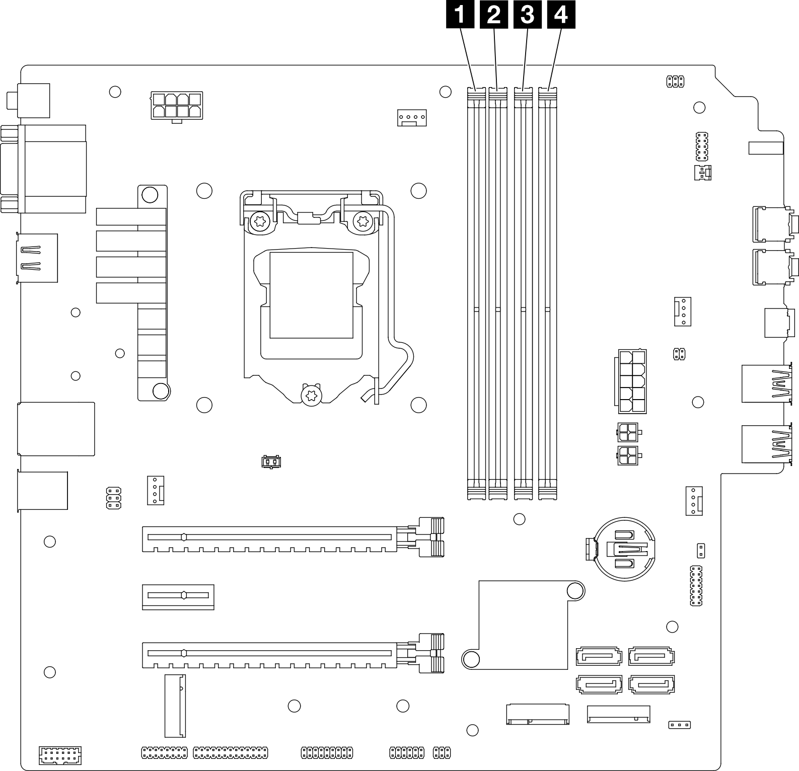
The following illustration shows the location of the memory module slots on the system board.

| 1 Memory module slot 1 | 3 Memory module slot 3 |
| 2 Memory module slot 2 | 4 Memory module slot 4 |
Independent mode
This server supports independent mode only.
Independent mode provides high performance memory capability. You can populate all channels with no matching requirements. Individual channels can run at different DIMM timings, but all channels must run at the same interface frequency.
All memory modules installed should be identical in type and capacity.
Do not mix memory modules with different voltages.
Do not mix low-voltage and regular UDIMMs. (2R memory module only)
For a list of supported Memory module slot options, see: Lenovo ServerProven website
| Total memory modules | Memory channel A | Memory channel B | |||
|---|---|---|---|---|---|
| Slot 1 | Slot 2 | Slot 3 | Slot 4 | ||
| 1 | V | ||||
| 2* | V | V | |||
| 4† | V | V | V | V | |
* See the following for the maximum memory speed supported:
† See the following for the maximum memory speed supported:
| |||||