Install an optical or tape drive
Follow this procedure to install an optical or RDX/LTO tape drive.
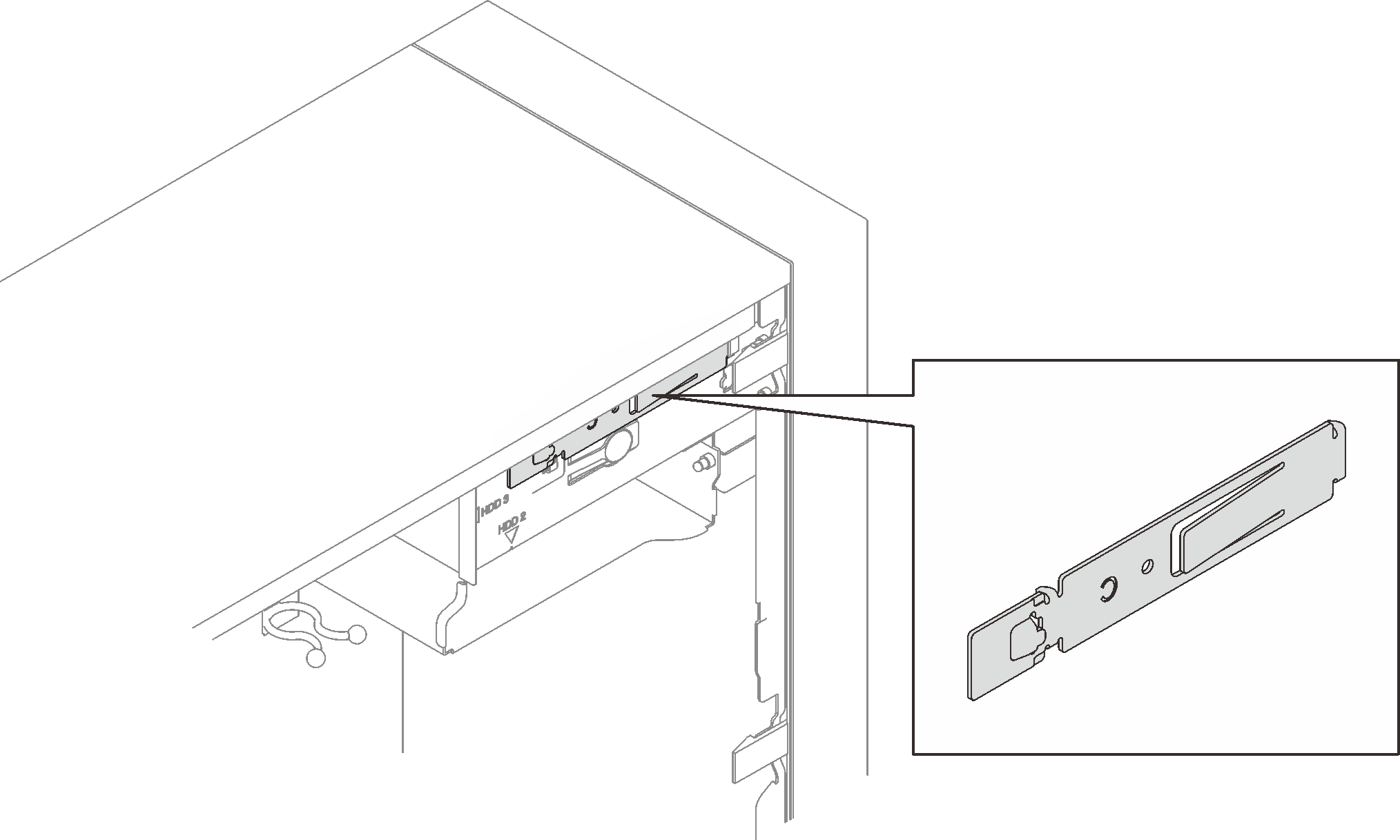
The retainer required for this procedure is stored on the side of the chassis, see the illustration below for its location. If the retainer is not available, contact Lenovo Support for the miscellaneous kit that includes the retainer.


- Do not remove the covers. Removing the covers of the laser product could result in exposure to hazardous laser radiation. There are no serviceable parts inside the device.
- Use of controls or adjustments or performance of procedures other than those specified herein might result in hazardous radiation exposure.
Before installing an optical or tape drive:
If the front bezel is installed, remove it (see Remove the front bezel).
Touch the static-protective package that contains the component to any unpainted metal surface on the server; then, remove it from the package and place it on a static-protective surface.
To install an optical or tape drive, complete the following steps:
- Align the retainer on the side of the optical or tape drive and install it.Figure 1. Installing the drive retainer to an optical drive
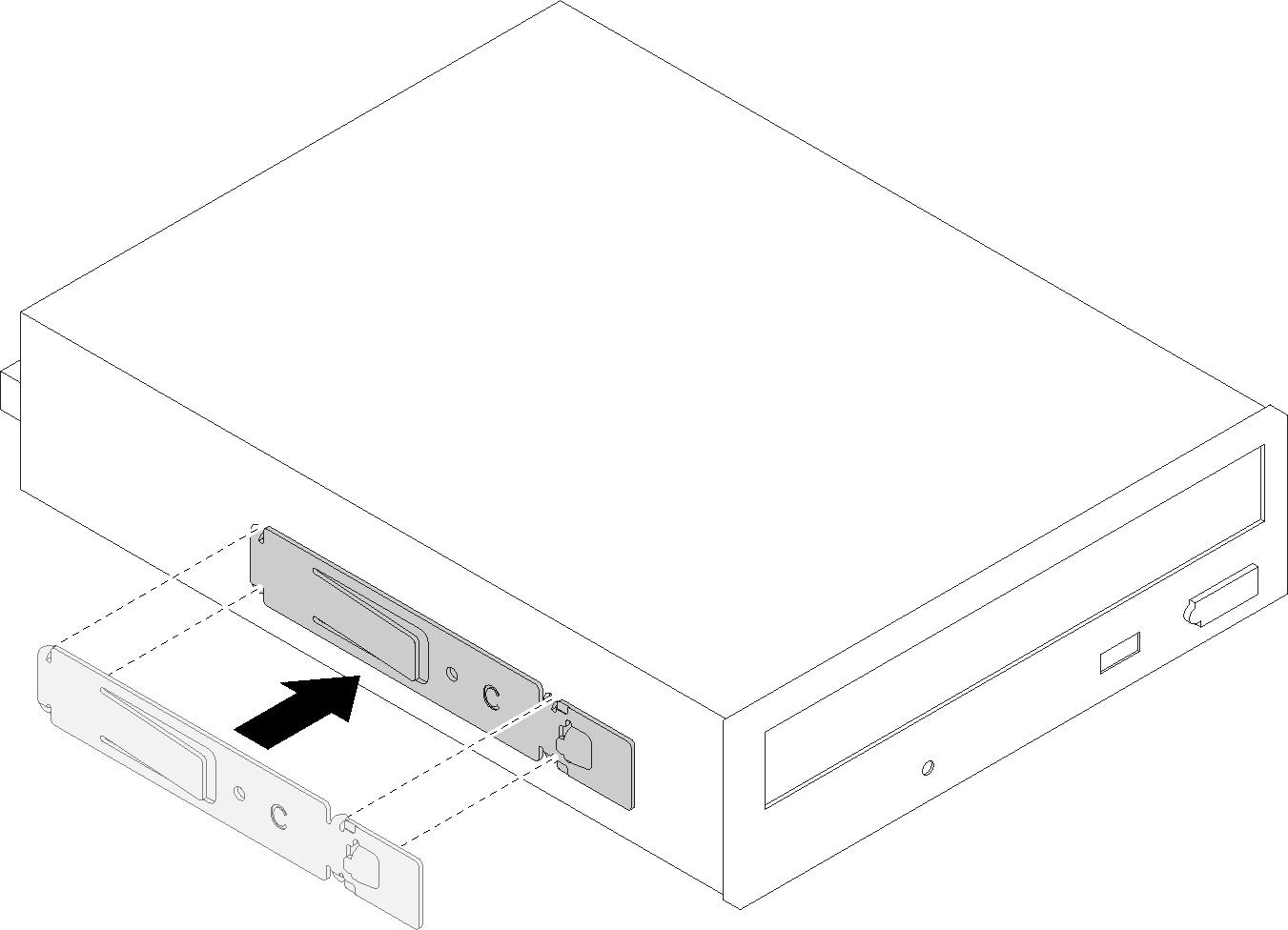 Figure 2. Installing the drive retainer to a tape drive
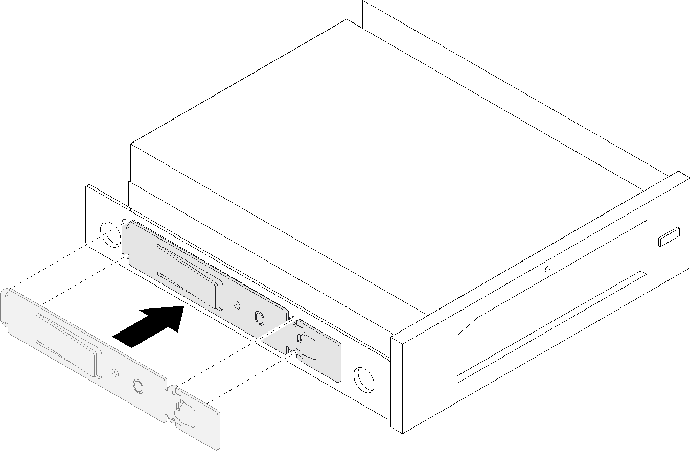
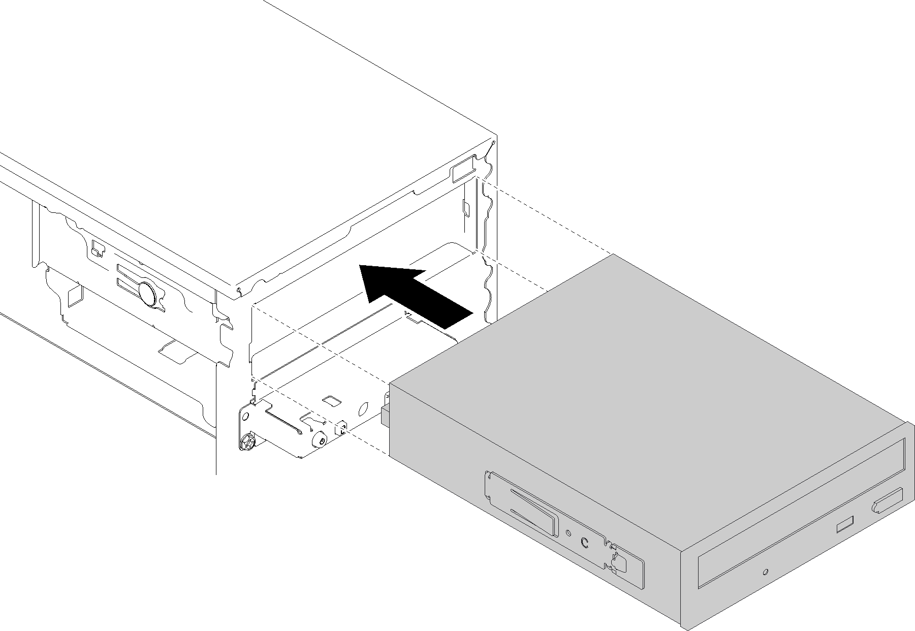
- Align the optical or tape drive to the drive bay, and slide it in until it snaps into place.Figure 3. Installing the optical drive assembly
After installing the optical or tape drive:
Install the front bezel (see Install the front bezel).
Proceed to complete the parts replacement (see Complete the parts replacement).
Demo video