Remove an optical or tape drive
Follow this procedure to remove an optical or RDX/LTO tape drive.


Read the safety information and installation guidelines (see Safety and Installation guidelines).
Turn off the server and peripheral devices, and disconnect the power cords and all external cables (see Power off the server).
If the server is in a rack, remove it from the rack.
Remove any locking device that secures the server cover, such as a Kensington lock or a pad lock.
- Remove the server cover (see Remove the server cover).CAUTIONThe heat sinks and processor could be very hot. To avoid from burning yourself, wait for a few minutes after turning off the server before you remove the server cover.
Remove the front bezel (see Remove the front bezel).
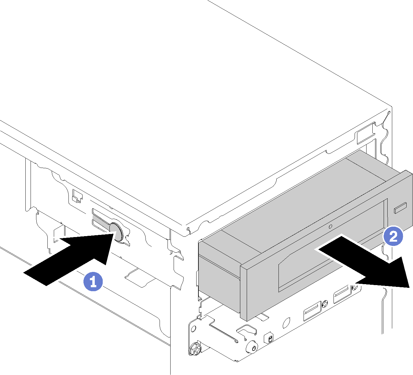
To remove an optical or tape drive, complete the following steps:
- Press the release tab on the side of the chassis, and slide the drive assembly out from the drive bay.Figure 1. Removing the optical drive assembly
After removing an optical or tape drive:
Install one of the following:
A optical or tape drive (see Install an optical or tape drive).
A 5.25-inch drive bay adapter (see Install a 5.25-inch drive bay adapter assembly).
Otherwise:
Store the drive retainer into the gap on the side of the chassis for future use.
Figure 2. Storing the drive retainer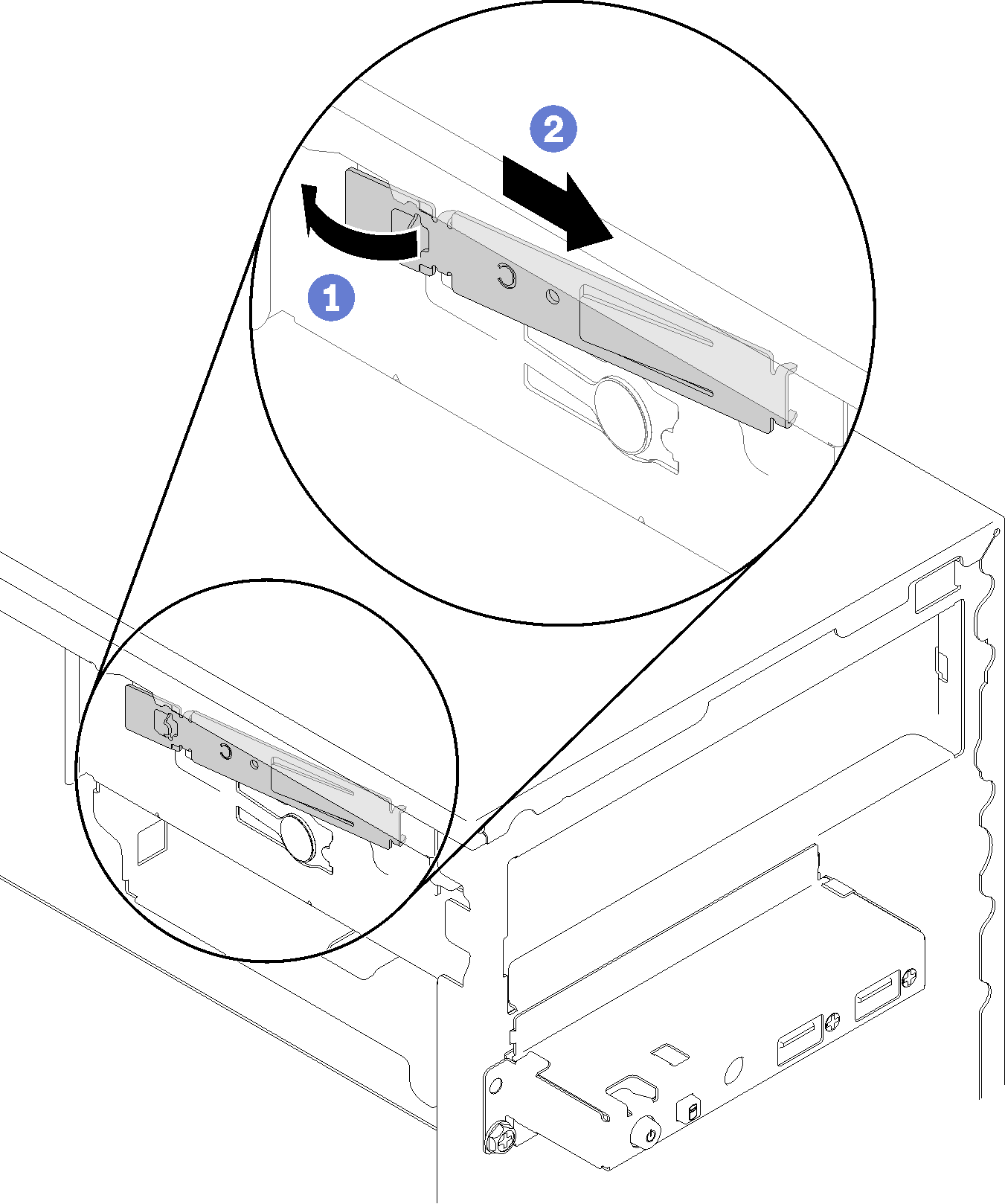
Install the shield into the drive bay.
Figure 3. Installing the drive bay shield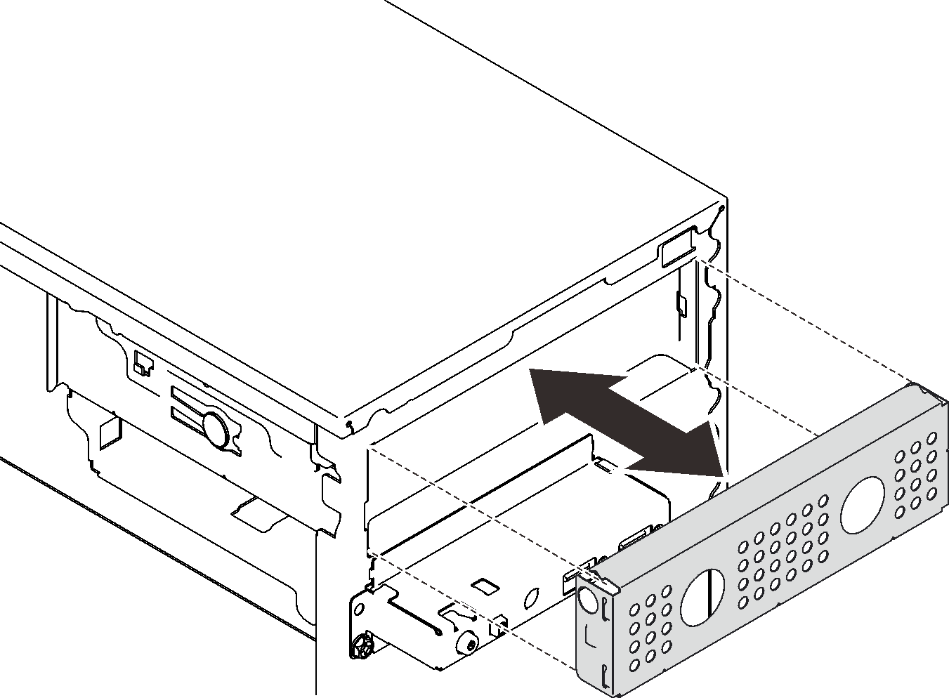
Press the filler into the slot on the front bezel until it snaps in place.
Figure 4. Installing the drive filler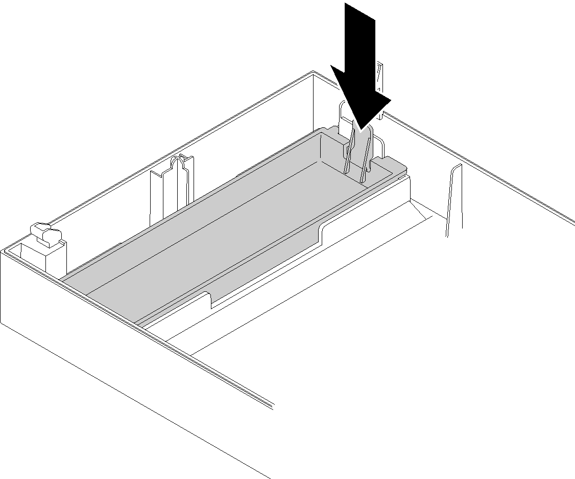
Install the front bezel (see Install the front bezel).
If you are instructed to return the component or optional device, follow all packaging instructions, and use any packaging materials for shipping that are supplied to you.
Demo video