Front view
The front view of the server varies by model.
Server models with twelve 3.5-inch simple-swap drive bays
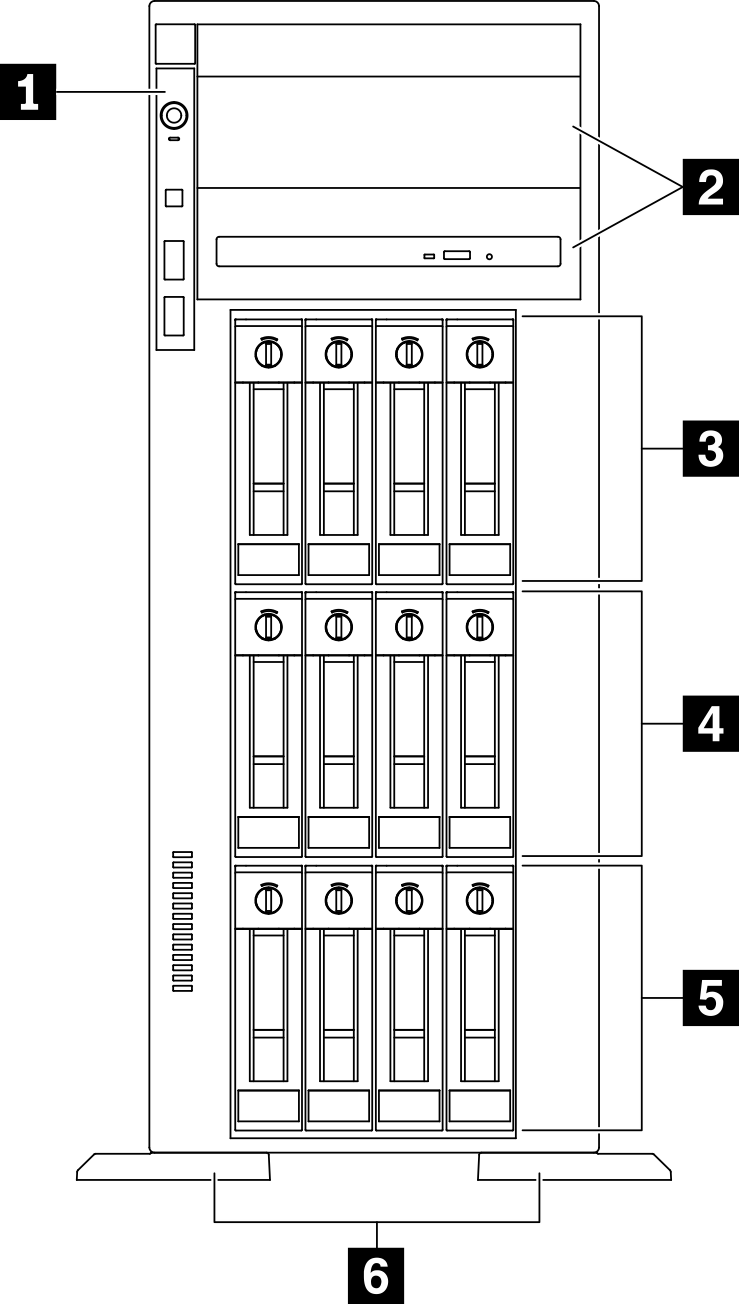
| 1 Front panel | 4 3.5-inch simple-swap drive bays 4-7 |
| 2 Optical-drive bays 1-2 | 5 3.5-inch simple-swap drive bays 0-3 |
| 3 3.5-inch simple-swap drive bays 8-11 | 6 Foot stands |
1 Front panel
For information about the controls, connectors, and status LEDs on the front panel, see Front panel.
2 Optical-drive bays 1-2
Depending on the model, your server might come with an optical drive installed in the lower 5.25-inch optical-drive bay. The upper 5.25-inch optical-drive bay is for a secondary optical drive or a tape drive. Some models have a secondary optical drive or a tape drive installed.
3 4 5 3.5-inch simple-swap drive bays
The drive bays are used to install 3.5-inch simple-swap drives. When you install drives, follow the order of the drive bay numbers. The EMI integrity and cooling of the server are protected by having all drive bays occupied. The vacant drive bays must be occupied by drive bay fillers or drive fillers.
6 Foot stands
For tower form factor models, the foot stands help the server stand steadily.
Server models with twelve 3.5-inch hot-swap drive bays
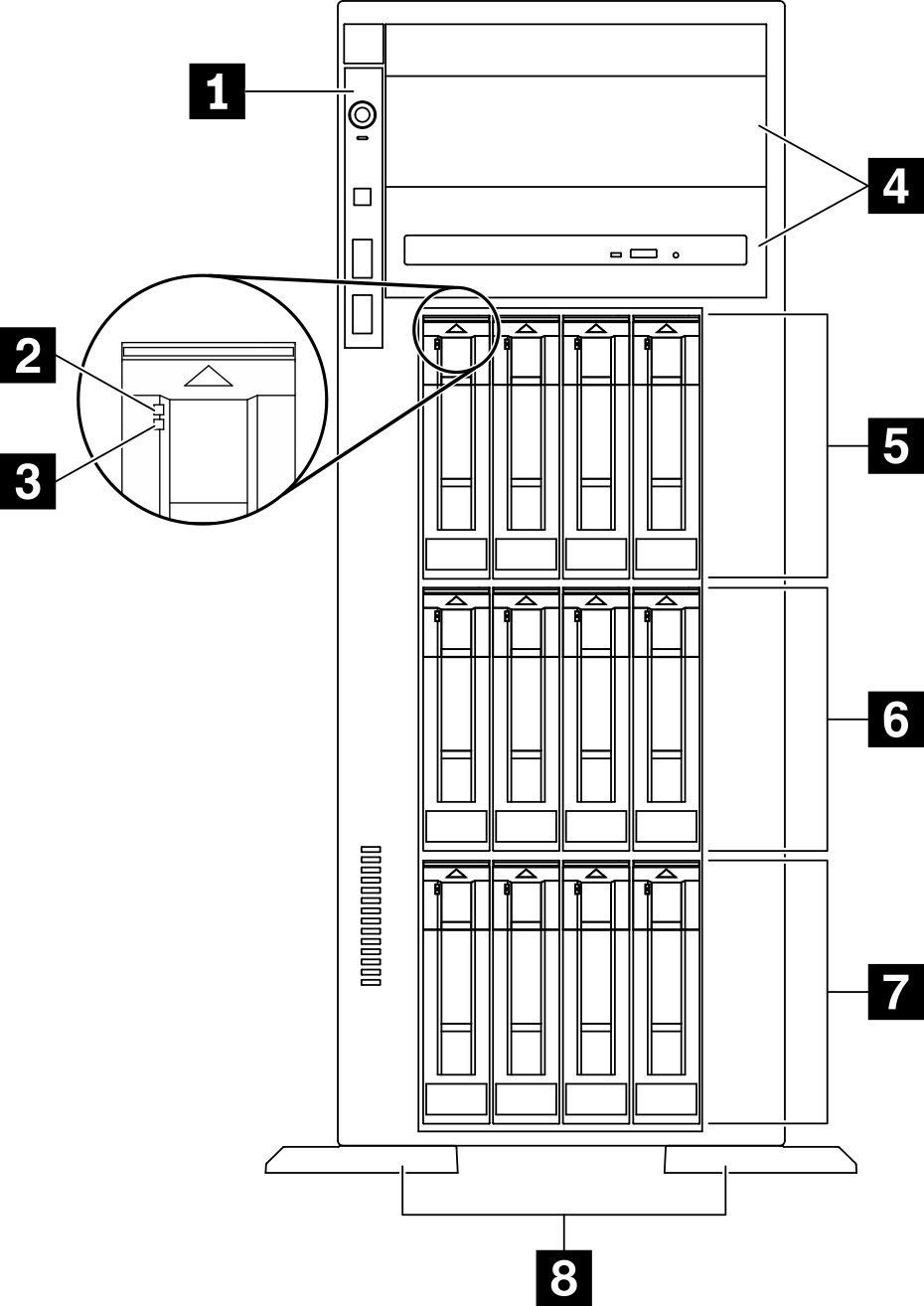
| 1 Front panel | 5 3.5-inch hot-swap drive bays 8-11 |
| 2 Drive activity LED (green) | 6 3.5-inch hot-swap drive bays 4-7 |
| 3 Drive status LED (yellow) | 7 3.5-inch hot-swap drive bays 0-3 |
| 4 Optical-drive bays 1-2 | 8 Foot stands |
1 Front panel
For information about the controls, connectors, and status LEDs on the front panel, see Front panel.
2 Drive activity LED (green)
Each hot-swap drive comes with an activity LED. When this LED is flashing, it indicates that the drive is in use.
3 Drive status LED (yellow)
- Lit: The drive has failed.
- Flashing slowly (once per second): The drive is being rebuilt.
- Flashing rapidly (three times per second): The drive is being identified.
4 Optical-drive bays 1-2
Depending on the model, your server might come with an optical drive installed in the lower 5.25-inch optical-drive bay. The upper 5.25-inch optical-drive bay is for a secondary optical drive or a tape drive. Some models have a secondary optical drive or a tape drive installed.
5 6 7 3.5-inch hot-swap drive bays
The drive bays are used to install 3.5-inch hot-swap drives. When you install drives, follow the order of the drive bay numbers. The EMI integrity and cooling of the server are protected by having all drive bays occupied. The vacant drive bays must be occupied by drive bay fillers or drive fillers.
8 Foot stands
For tower form factor models, the foot stands help the server stand steadily.
Server models with sixteen 3.5-inch hot-swap drive bays
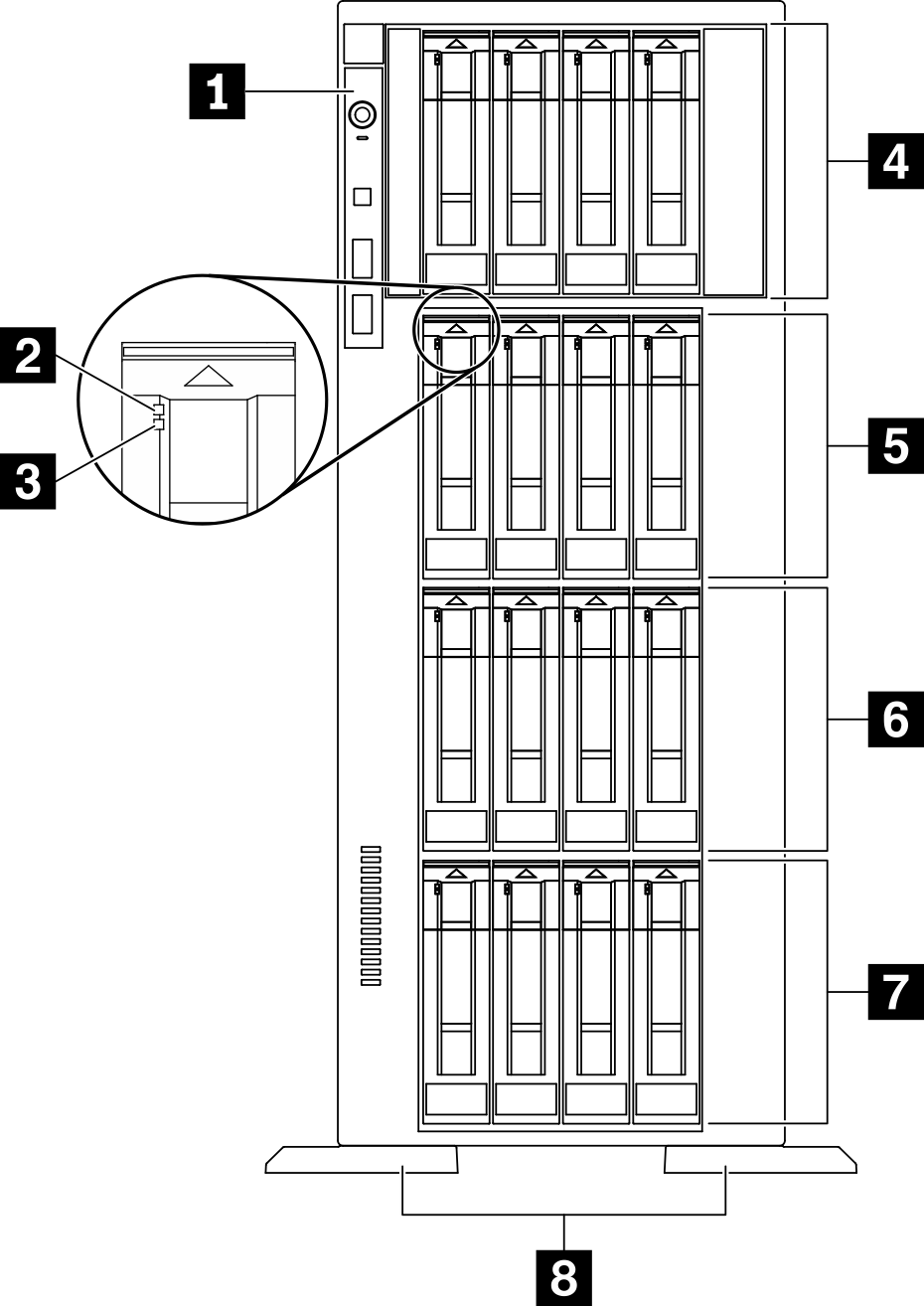
| 1 Front panel | 5 3.5-inch hot-swap drive bays 8-11 |
| 2 Drive activity LED (green) | 6 3.5-inch hot-swap drive bays 4-7 |
| 3 Drive status LED (yellow) | 7 3.5-inch hot-swap drive bays 0-3 |
| 4 3.5-inch hot-swap drive bays 12-15 | 8 Foot stands |
1 Front panel
For information about the controls, connectors, and status LEDs on the front panel, see Front panel.
2 Drive activity LED (green)
Each hot-swap drive comes with an activity LED. When this LED is flashing, it indicates that the drive is in use.
3 Drive status LED (yellow)
- Lit: The drive has failed.
- Flashing slowly (once per second): The drive is being rebuilt.
- Flashing rapidly (three times per second): The drive is being identified.
4 5 6 7 3.5-inch hot-swap drive bays
The drive bays are used to install 3.5-inch hot-swap drives. When you install drives, follow the order of the drive bay numbers. The EMI integrity and cooling of the server are protected by having all drive bays occupied. The vacant drive bays must be occupied by drive bay fillers or drive fillers.
8 Foot stands
For tower form factor models, the foot stands help the server stand steadily.
Server models with thirty-two 2.5-inch drive bays
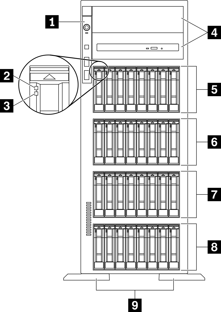
| 1 Front panel | 6 2.5-inch hot-swap dive bays 16-23 |
| 2 Drive activity LED (green) | 7 2.5-inch hot-swap drive bays 8-15 |
| 3 Drive status LED (yellow) | 8 2.5-inch hot-swap drive bays 0-7 |
| 4 Optical-drive bays 1-2 | 9 Foot stands |
| 5 2.5-inch hot-swap drive bays 24-31 |
1 Front panel
For information about the controls, connectors, and status LEDs on the front panel, see Front panel.
2 Drive activity LED (green)
Each hot-swap drive comes with an activity LED. When this LED is flashing, it indicates that the drive is in use.
3 Drive status LED (yellow)
- Lit: The drive has failed.
- Flashing slowly (once per second): The drive is being rebuilt.
- Flashing rapidly (three times per second): The drive is being identified.
4 Optical-drive bays 1-2
Depending on the model, your server might come with an optical drive installed in the lower 5.25-inch optical-drive bay. The upper 5.25-inch optical-drive bay is for a secondary optical drive or a tape drive. Some models have a secondary optical drive or a tape drive installed.
5 6 7 8 2.5-inch hot-swap drive bays
The drive bays are used to install 2.5-inch hot-swap drives. When you install drives, follow the order of the drive bay numbers. The EMI integrity and cooling of the server are protected by having all drive bays occupied. The vacant drive bays must be occupied by drive bay fillers or drive fillers.
9 Foot stands
For tower form factor models, the foot stands help the server stand steadily.