Rear view
The rear of the server provides access to several connectors and components.
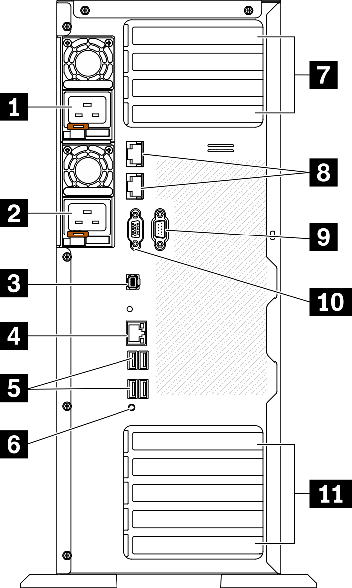
| 1 Hot-swap power supply 1 | 7 PCIe slots 1-4 (top to bottom) |
| 2 Hot-swap power supply 2 (optional) | 8 10Gb ethernet connectors (2) |
| 3 External LCD diagnostics handset connector | 9 Serial-port-module slot |
| 4 XClarity Controller network connector | 10 VGA connector |
| 5 Four USB 3.2 Gen 1 connectors (4) | 11 PCIe slots 5-9 (top to bottom) |
| 6 NMI button |
1 2 Hot-swap power supplies
Install power supply units to these bays, connect them to power cords. Make sure the power cords are connected properly.
You can purchase a power supply option from Lenovo and install the power supply to provide power redundancy without turning off the server.
On each power supply, there are three status LEDs near the power cord connector. For information about the status LEDs, see Rear view LEDs.
3 External LCD diagnostics handset connector
Connect the external LCD diagnostics handset here. See External LCD diagnostics handset for more details.
4 XClarity Controller network connector
Used to attach an Ethernet cable to manage the system using XClarity Controller.
5 USB 3.2 Gen 1 connectors
Used to attach a device that requires a USB 2.0 or 3.2 Gen 1 connection, such as a keyboard, a mouse, or a USB flash drive.
6 NMI button
Press this button to force a nonmaskable interrupt to the processor. You might have to use a pen or the end of a straightened paper clip to press the button. You can also use it to force a blue-screen memory dump. Use this button only when you are directed to do so by Lenovo Support.
7 PCIe slots 1-4 (top to bottom)
- Slot 1: PCIe4 x16, 75W, Full-height, half-length
- Slot 2: PCIe4 x8 (open end), 75W, Full-height, half-length
- Slot 3: PCIe4 x16, 75W, Full-height, half-length
- Slot 4: PCIe4 x8 (open end), 75W, Full-height, half-length
8 10Gb Ethernet connector
Used to attach a 10Gb Ethernet cable. Each 10Gb Ethernet connector has two status LEDs to help you identify the Ethernet connectivity and activity. For more information, see Rear view LEDs.
9 Serial-port-module slot
Connect a 9-pin serial device to this connector. The serial port is shared with the XCC. The XCC can take control of the shared serial port to redirect serial traffic, using Serial over LAN (SOL).
10 VGA connector
Used to attach a VGA-compatible video device, such as a VGA monitor.
11 PCIe slots 5-9 (top to bottom)
- Slot 5: PCIe4 x16, 75W, Full-height, half-length
- Slot 6: PCIe4 x8 (open end), 75W, Full-height, half-length
- Slot 7: PCIe4 x16, 75W, Full-height, half-length
- Slot 8: PCIe3 x8 (open end), 75W, Full-height, half-length (requires additional cable connection, see PCIe slot 8 cable routing)
- Slot 9: PCIe4 x8 (open end), 75W, Full-height, half-length