Cabling a single-interconnect configuration
Procedures for cabling theThinkAgile CP single-interconnect switch configuration.
Complete these procedures to cable a single-interconnect configuration.
Hardware management network connections
Connect the following ports to the management switch:
Interconnect port 47 using a SFP+ Direct Attach Cable (DAC)
Compute block port (C.M.) using a RJ45 patch cable
Upper storage block port (S.U.M.) using a RJ45 patch cable
Lower storage block port (S.L.M.) using a RJ45 patch cable
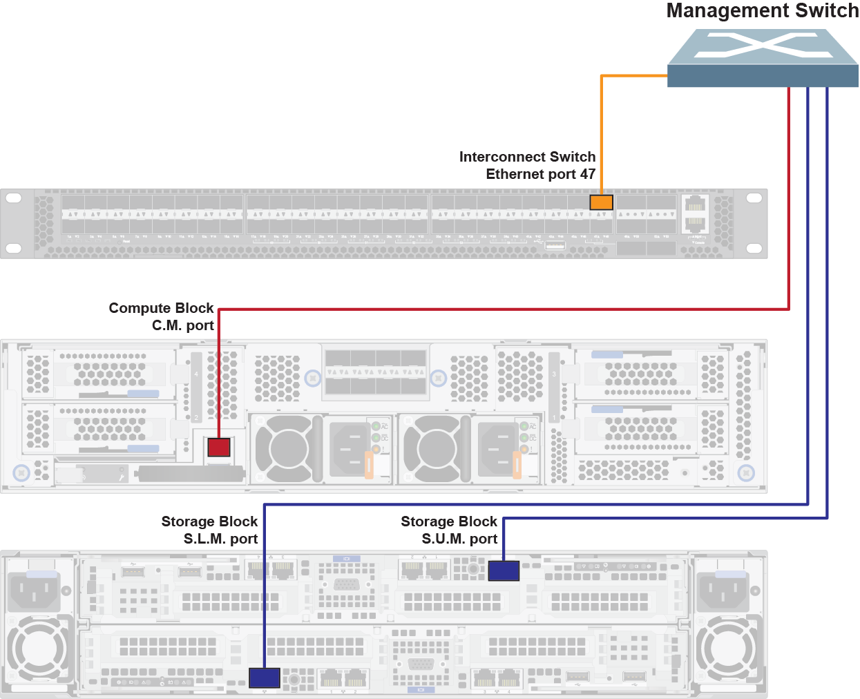
If not using the Lenovo ThinkSystem NE0152T RackSwitch as the management switch, you may require different cables for the management network connections.
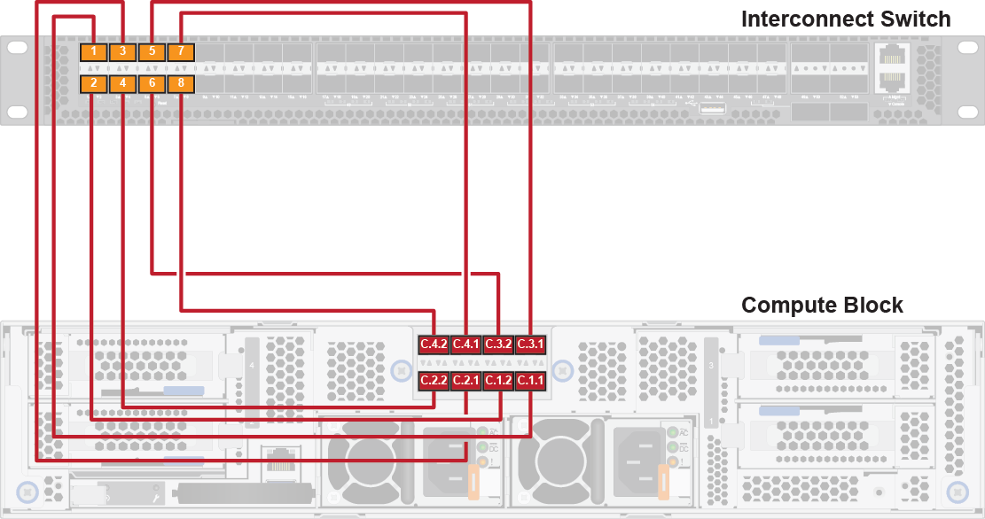
Compute block connections (single-interconnect configuration)
The compute block consists of an enclosure with up to four compute nodes, which are numbered as follows:

Connect the compute nodes according to the populated compute node location and corresponding port mapping. The cables to be used are clearly labeled; make sure that you use the correct cables.
You need two SFP+ Direct Attach Cables (DACs) for each populated compute node.
The compute block port mapping is as follows:
Front compute node location | Back network port mapping | Network interconnect port |
|---|---|---|
Top left | Compute node 3, port 1 (C.3.1) | Interconnect, port 5 |
Compute node 3, port 2 (C.3.2) | Interconnect, port 6 | |
Top right | Compute node 4, port 1 (C.4.1) | Interconnect, port 7 |
Compute node 4, port 2 (C.4.2) | Interconnect, port 8 | |
Bottom left | Compute node 1, port 1 (C.1.1) | Interconnect, port 1 |
Compute node 1, port 2 (C.1.2) | Interconnect, port 2 | |
Bottom right | Compute node 2, port 1 (C.2.1) | Interconnect, port 3 |
Compute node 2, port 2 (C.2.2) | Interconnect, port 4 |
You only need to cable the number of compute nodes that are installed in the compute enclosure.
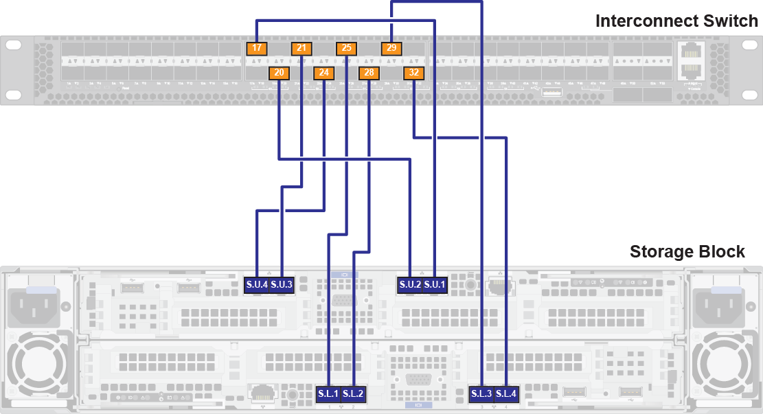
Storage block connections (single-interconnect configuration)
Connect the storage controllers according to the populated controller location and corresponding port mapping. The cables to be used are clearly labeled; make sure that you use the correct cables.
You need eight Category 6 patch cables and eight SFP+ transceivers. Attach a single SFP+ transceiver to each patch cable.
The storage block port mapping is as follows:
Front storage controller location | Back network port mapping | Network interconnect port |
|---|---|---|
Upper | Upper storage controller, port 1 (S.U.1) | Interconnect, port 17 |
Upper storage controller, port 2 (S.U.2) | Interconnect, port 20 | |
Upper storage controller, port 3 (S.U.3) | Interconnect, port 21 | |
Upper storage controller, port 4 (S.U.4) | Interconnect, port 24 | |
Lower | Lower storage controller, port 1 (S.L.1) | Interconnect, port 25 |
Lower storage controller, port 2 (S.L.2) | Interconnect, port 28 | |
Lower storage controller, port 3 (S.L.3) | Interconnect, port 29 | |
Lower storage controller, port 4 (S.L.4) | Interconnect, port 32 |