Replacing the system board
Use this information to replace the system board.
Note
- When you reassemble the components in the server, be sure to route all cables carefully so that they are not exposed to excessive pressure.
- When you replace the system board, you must either update the server with the latest firmware or restore the pre-existing firmware that the customer provides on a diskette or CD image. The vital product data (VPD) must also be updated. Make sure that you have the latest firmware or a copy of the pre-existing firmware before you proceed. See Updating the firmware and Updating the DMI/SMBIOS data for more information.AttentionInstalling the wrong firmware or device-driver update might cause the server to malfunction. Before you install a firmware or device-driver update, read any readme and change history files that are provided with the downloaded update. These files contain important information about the update and the procedure for installing the update, including any special procedure for updating from an early firmware or device-driver version to the latest version.
- Reactivate any Features on Demand features. Instructions for automating the activation of features and installing activation keys is in the Lenovo System x Features on Demand Users Guide. To download the document, go to the Lenovo Features on Demand website, log in, and click Help.
Important
Some cluster solutions require specific code levels or coordinated code updates. If the device is part of a cluster solution, verify that the latest level of code is supported for the cluster solution before you update the code.
To install the system board on the 4U server model with non-hot-swap power supplies, complete the following steps. For 5U server models with hot-swap power supplies, please see the next sub-section.
- Read the safety information in Safety and Installation guidelines.
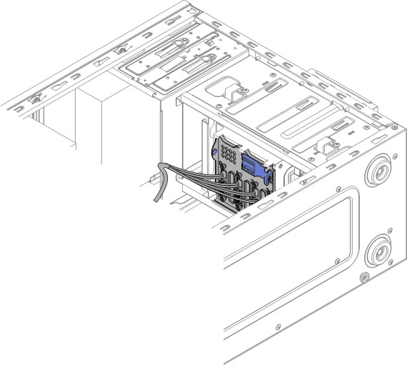
- Pull the hard disk drive cage half out of the chassis.Figure 1. Pulling hard disk drive cage half out of chassis for 4U server model with non-hot-swap power supplies
- Touch the static-protective package that contains the system board to any unpainted metal surface on the server. Then, remove the system board from the package.
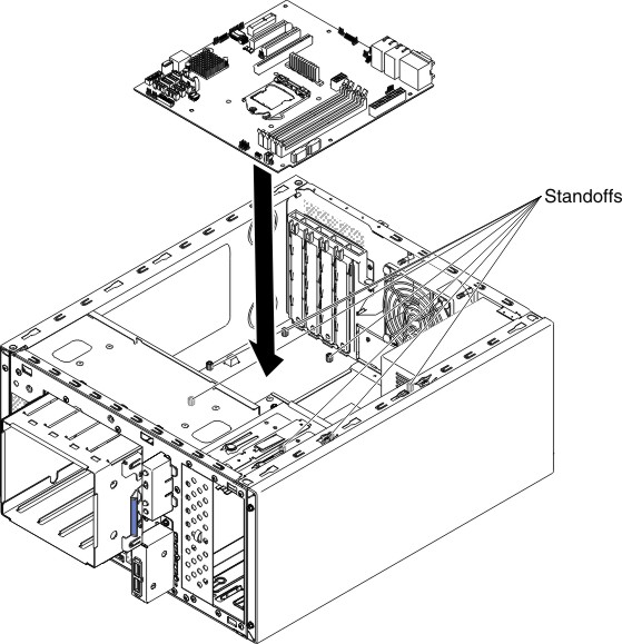
- Lower the system board into the chassis. Pay attention to the positions of the standoffs as they will be used later.Figure 2. System board installation for 4U server model with non-hot-swap power supplies
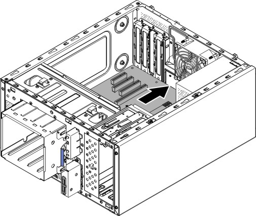
- Gently push the system board by the side nearest to the fan cage to insert the external input/output connectors into their respective holes in the chassis.Figure 3. Pushing external input/output connectors into chassis for 4U server model with non-hot-swap power supplies
 AttentionWhen inserting the system board external input/output connectors into their respective holes in the chassis, make sure the EMC springs are not inserted into the holes. Inserting the EMC springs into the holes in the chassis could damage the EMC springs.Figure 4. How to correctly insert EMC springs
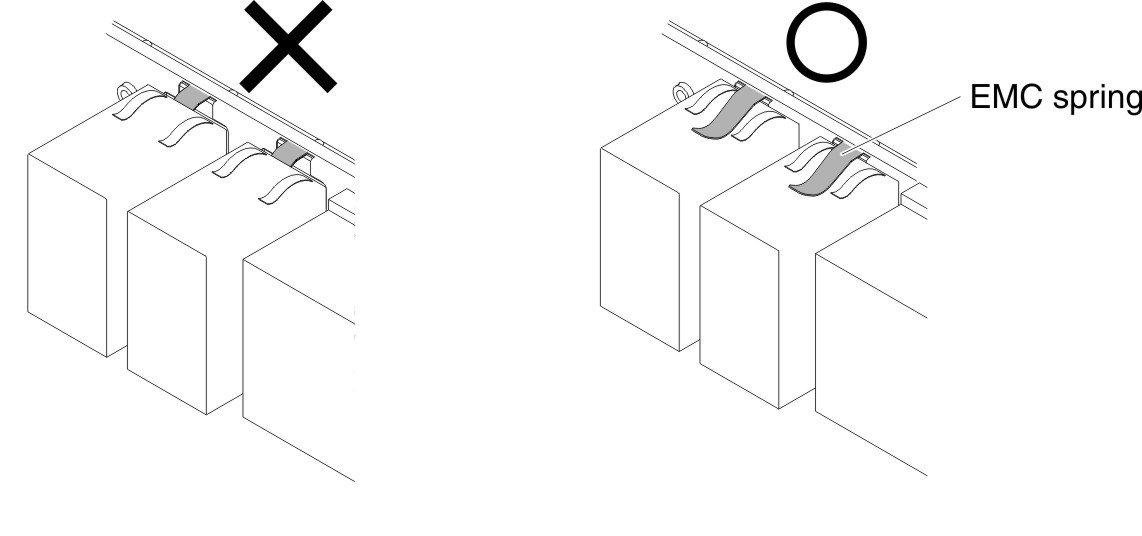
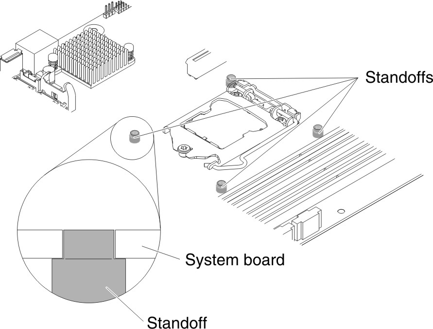
- Align the holes (seven in total) on the system board with the respective standoffs on the chassis.Figure 5. System board alignment with respective standoffs on chassis for 4U server model with non-hot-swap power supplies
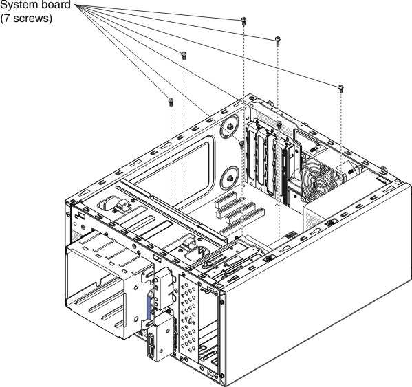
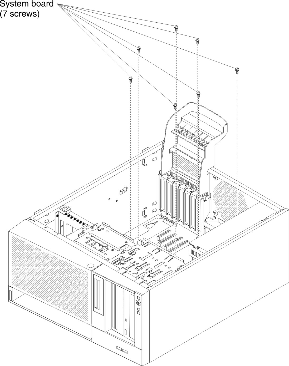
- Install the seven screws that secure the system board to the chassis.Figure 6. System board screw installation for 4U server model with non-hot-swap power supplies
- Install any of the following components that you removed from the system board:
- Battery (see Replacing the system battery).
- DIMMs (see Replacing a memory module).
- Microprocessor and heat sink (see Replacing the microprocessor and heat sink).
- Adapters (see Replacing an adapter).
- USB embedded hypervisor flash device (see Replacing the USB embedded hypervisor flash device).
- Reconnect any cables to the system board that you disconnected during removal (see System-board internal connectors).
- Secure the cables with the retention-clips.
- Press the hard disk drive cage in until the release latches click into place.
- Install the air baffle (see Replacing the air baffle).
- Install the side cover (see Replacing the side cover).
- Stand the server back up in its vertical position.
- Install bezel (see Replacing the bezel).
- Reconnect the external cables and power cords; then, turn on the attached devices and turn on the server.ImportantPerform the following updates:
- Either update the server with the latest RAID firmware or restore the pre-existing firmware from a diskette or CD image.
- Update the UUID (see Updating the Universal Unique Identifier (UUID)).
- Update the DMI/SMBIOS (see Updating the DMI/SMBIOS data).
- Reactivate any Features on Demand features.
To install the system board on the 5U server model with hot-swap power supplies, complete the following steps. For 4U server models with non-hot-swap power supplies, please see the above sub-section.
- Read the safety information in Safety and Installation guidelines.
- Touch the static-protective package that contains the system board to any unpainted metal surface on the server. Then, remove the system board from the package.
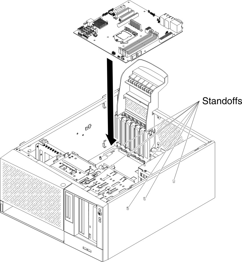
- Lower the system board into the chassis. Pay attention to the positions of the standoffs as they will be used later.Figure 7. System board installation for 5U server model with hot-swap power supplies
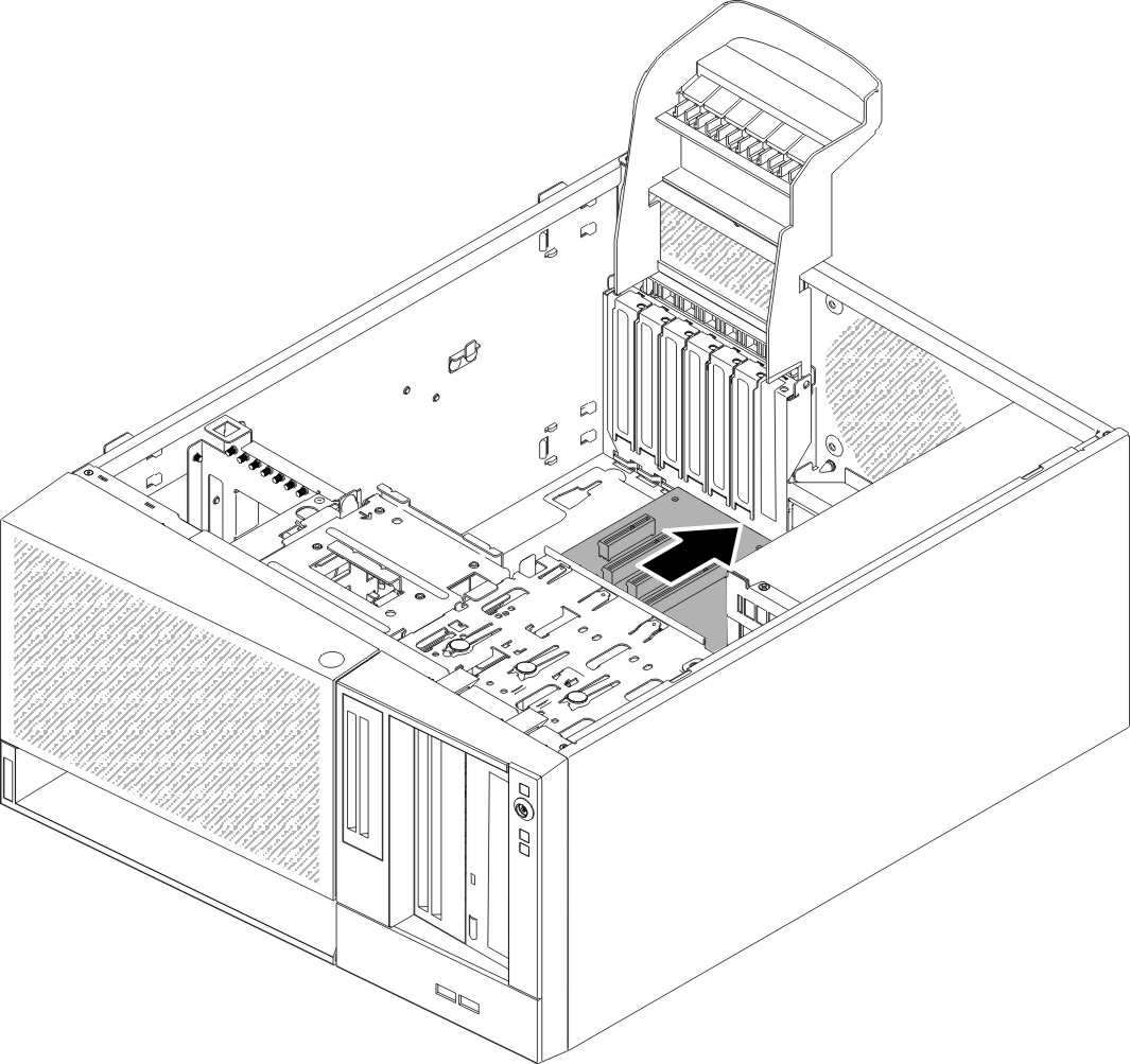
- Gently push the system board by the side nearest to the fan cage to insert the external input/output connectors into their respective holes in the chassis.Figure 8. Pushing external input/output connectors into chassis for 5U server model with hot-swap power supplies
 AttentionWhen inserting the system board external input/output connectors into their respective holes in the chassis, make sure the EMC springs are not inserted into the holes. Inserting the EMC springs into the holes in the chassis could damage the EMC springs.Figure 9. How to correctly insert EMC springs
 - Align the holes (seven in total) on the system board with the respective standoffs on the chassis.Figure 10. System board alignment with respective standoffs on chassis for 5U server model with hot-swap power supplies

- Install the seven screws that secure the system board to the chassis.Figure 11. System board screw installation for 5U server model with hot-swap power supplies
- Install any of the following components that you removed from the system board:
- Adapters (see Replacing an adapter).
- Battery (see Replacing the system battery).
- DIMMs (see Replacing a memory module).
- Microprocessor and heat sink (see Replacing the microprocessor and heat sink).
- USB embedded hypervisor flash device (see Replacing the USB embedded hypervisor flash device).
- Reconnect any cables to the system board that you disconnected during removal (see System-board internal connectors).
- Secure the cables with the retention-clips.
- Install the hard disk drive fan duct (see Replacing the hard disk drive fan duct).
- Rotate the rear adapter-retention bracket to the closed (locked) position.
- Stand the server back up in its vertical position.
- Install and lock the side cover (see Replacing the side cover).
- Reconnect the external cables and power cords; then, turn on the attached devices and turn on the server.ImportantPerform the following updates:
- Either update the server with the latest RAID firmware or restore the pre-existing firmware from a diskette or CD image.
- Update the UUID (see Updating the Universal Unique Identifier (UUID)).
- Update the DMI/SMBIOS (see Updating the DMI/SMBIOS data).
- Reactivate any Features on Demand features.
Give documentation feedback