Removing the system board
Use this information to remove the system board.
Before you remove the system board from the server, take the following steps to save data, firmware, and configuration data:
- Record all system configuration information, such as IMM IP addresses, vital product data, and the machine type, model number, serial number, Universally Unique Identifier, and asset tag of the server.
- Using the Advanced Settings Utility (ASU), save the system configuration to external media.
- Save the system-event log to external media.
Note
When you replace the system board, you must either update the server with the latest firmware or restore the pre-existing firmware that the customer provides on a CD or DVD image. Make sure that you have the latest firmware or a copy of the pre-existing firmware before you proceed.
To remove the system board on the 4U server model with non-hot-swap power supplies, complete the following steps. For 5U server models with hot-swap power supplies, please see the next sub-section.
- Read the safety information in Safety and Installation guidelines.
- Turn off the server and all peripheral devices; then, disconnect the power cords and all external cables.
- Carefully turn the server on its side so that it is lying flat, with the cover facing up.AttentionDo not allow the server to fall over.
- Remove the side cover (see Removing the side cover).
- Remove the air baffle (see Removing the air baffle).
- Remove the microprocessor and heat sink (see Removing the microprocessor and heat sink).AttentionRemove the socket covers from the microprocessor sockets on the new system board and place them on the microprocessor sockets of the system board you are removing.
- Pull the hard disk drive cage half out of the chassis.Figure 1. Pulling hard disk drive cage half out of chassis for 4U server model with non-hot-swap power supplies
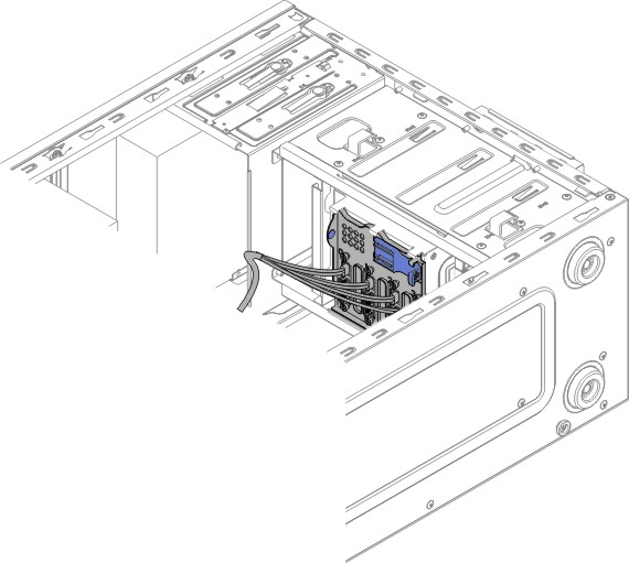
- Disengage the cables from any retention-clips.
- Note where each cable is connected; then, disconnect all cables from the system board.AttentionDisengage all latches, release tabs or locks on cable connectors when you disconnect all cables from the system board. Failing to release them before removing the cables will damage the cable sockets on the system board. The cable sockets on the system board are fragile. Any damage to the cable sockets may require replacing the system board.
- Remove any of the following components (in addition to others that might not be listed) that are installed on the system board and put them in a safe, static-protective place:
- Adapters (see Removing an adapter).
- DIMMs (see Replacing a memory module).
- Battery (see Removing the system battery).
- USB embedded hypervisor flash device (see Removing the USB embedded hypervisor flash device).
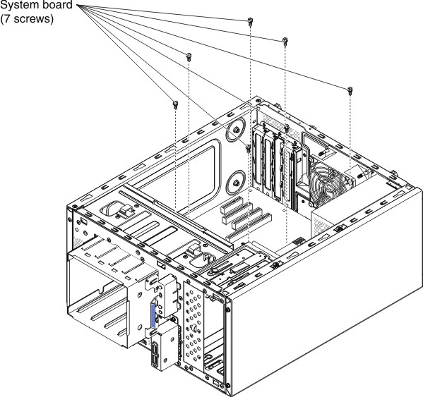
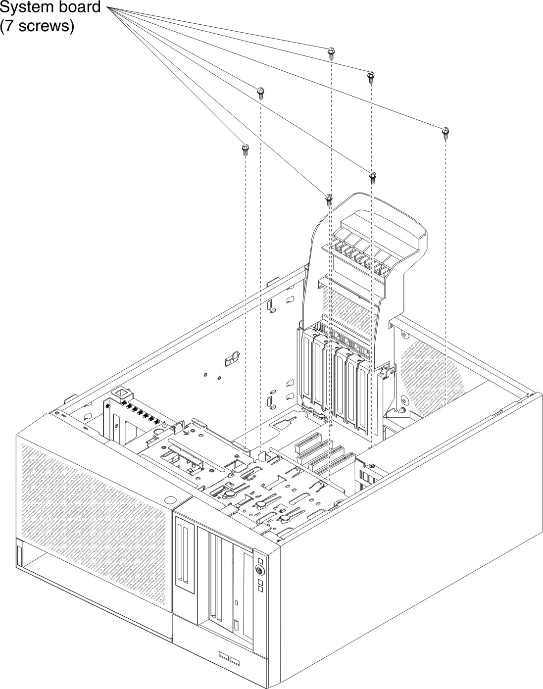
- Remove the seven screws that secure the system board to the chassis.Figure 2. System board screw removal for 4U server model with non-hot-swap power supplies
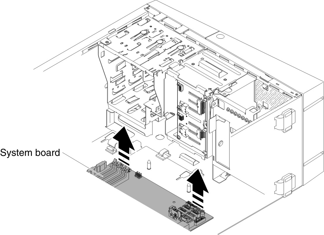
- Slightly lift the system board at the side that is near the hard disk drive cage to create a small angle of elevation between the system board and chassis.Figure 3. Slightly lifting system board for 4U server model with non-hot-swap power supplies
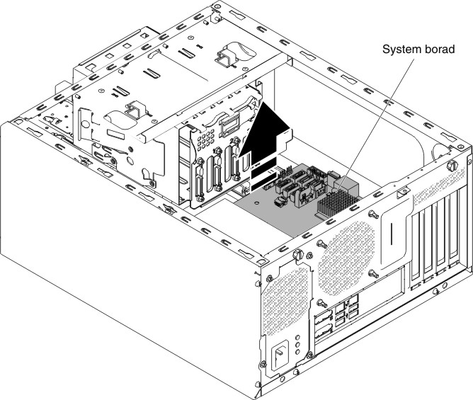
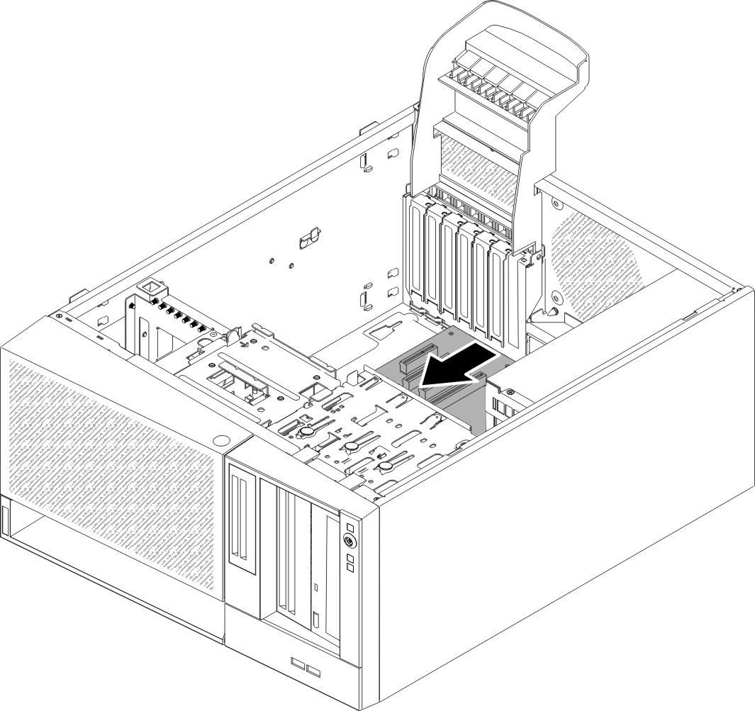
- Gently push the external input/output connectors out of their respective holes in the chassis.Figure 4. Pushing external input/output connectors out of chassis for 4U server model with non-hot-swap power supplies
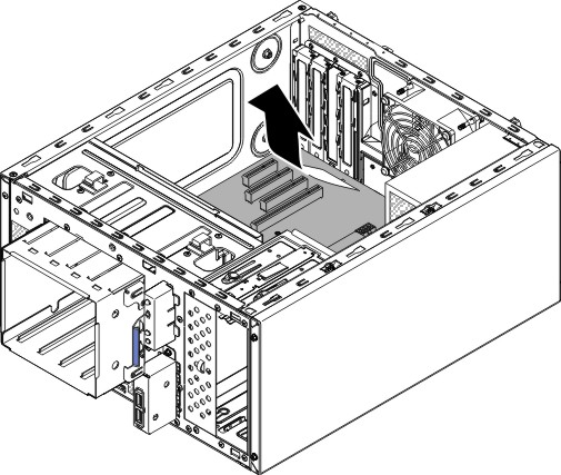
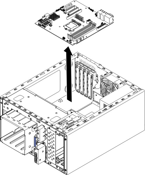
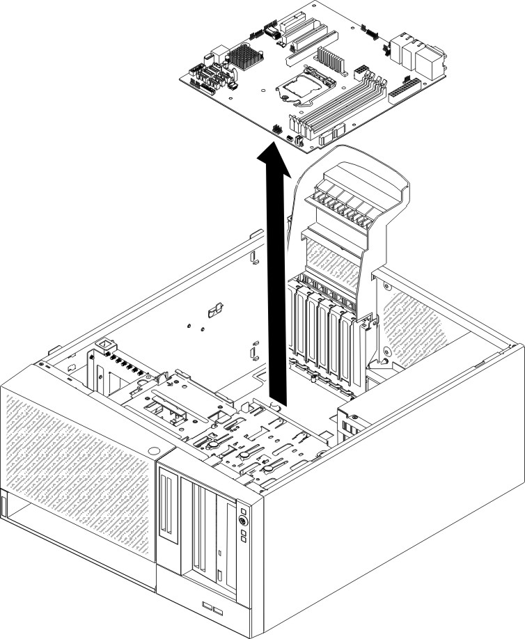
- Grasp the system board by the edges; then, carefully lift up the system board and remove it from the chassis, being careful not to damage any surrounding components.Figure 5. System board removal for 4U server model with non-hot-swap power supplies
- If you are instructed to return the system board, follow all packaging instructions, and use any packaging materials for shipping that are supplied to you.AttentionMake sure to place the socket covers for the microprocessor sockets on the system board before returning the system board.
To remove the system board on the 5U server model with hot-swap power supplies, complete the following steps. For 4U server models with non-hot-swap power supplies, please see the above sub-section.
- Read the safety information in Safety and Installation guidelines.
- Turn off the server and all attached devices; then, disconnect all power cords and external cables.
- Unlock and remove the side cover (see Removing the side cover).
- Carefully turn the server on its side so that it is lying flat, with the system board facing up.AttentionDo not allow the server to fall over.
- Rotate the rear adapter-retention bracket to the open (unlocked) position.
- Remove the hard disk drive fan duct (see Removing the hard disk drive fan duct).
- Remove the microprocessor and heat sink (see Removing the microprocessor and heat sink).AttentionRemove the socket covers from the microprocessor sockets on the new system board and place them on the microprocessor sockets of the system board you are removing.
- Disengage the cables from any retention-clips.
- Note where each cable is connected; then, disconnect all cables from the system board.AttentionDisengage all latches, release tabs or locks on cable connectors when you disconnect all cables from the system board. Failing to release them before removing the cables will damage the cable sockets on the system board. The cable sockets on the system board are fragile. Any damage to the cable sockets may require replacing the system board.
- Remove any of the following components (in addition to others that might not be listed) that are installed on the system board and put them in a safe, static-protective place:
- Adapters (see Removing an adapter).
- DIMMs (see Replacing a memory module).
- Battery (see Removing the system battery).
- USB embedded hypervisor flash device (see Removing the USB embedded hypervisor flash device).
- Remove the seven screws that secure the system board to the chassis.Figure 6. System board screw removal for 5U server model with hot-swap power supplies
- Slightly lift the system board at the side that is near the hard disk drive cage to create a small angle of elevation between the system board and chassis.Figure 7. Slightly lifting system board for 5U server model with hot-swap power supplies
- Gently push the external input/output connectors out of their respective holes in the chassis.Figure 8. Pushing external input/output connectors out of chassis for 5U server model with hot-swap power supplies
- Grasp the system board by the edges; then, carefully lift up the system board and remove it from the chassis, being careful not to damage any surrounding components.Figure 9. System board removal for 5U server model with hot-swap power supplies
- If you are instructed to return the system board, follow all packaging instructions, and use any packaging materials for shipping that are supplied to you.AttentionMake sure to place the socket covers for the microprocessor sockets on the system board before returning the system board.
Give documentation feedback