Installing a memory module
The following notes describe the types of DIMMs that the server supports and other information that you must consider when you install DIMMs.
- Confirm that the server supports the DIMM that you are installing, see the Lenovo ServerProven website.
- The server supports only industry-standard double-data-rate 3 (DDR3), 1066 MHz PC3-8500, 1333 MHz PC3-10600, or 1600 MHz PC3-12800, (single-rank, dual-rank, or quad-rank in specified models), registered or unbuffered, synchronous dynamic random-access memory (SDRAM) dual inline memory modules (DIMMs) with error correcting code (ECC).
- The specifications of a DDR3 DIMM are on a label on the DIMM, in the following format.
gggggeRxff-PC3v-wwwwwm-aa-bb-ccd
where:- ggggg is the total capacity of the DIMM (for example, 1GB, 2GB, or 4GB)
- eR is the number of ranks
- 1R = single-rank
- 2R = dual-rank
- 4R = quad-rank
- x ff is the device organization or bit width (for example, x4, x8, or x16)
- 4 = x4 organization (4 DQ lines per SDRAM)
- 8 = x8 organization
- 16 = x16 organization
- wwwww is the DIMM bandwidth, in MBps
- 8500 = 8.53 GBps (DDR3-1066 SDRAMs, 8-byte primary data bus)
- 10600 = 10.66 GBps (DDR3-1333 SDRAMs, 8-byte primary data bus)
- 12800 = 12.80 GBps (DDR3-1600 SDRAMs, 8-byte primary data bus)
- 14900 = 14.93 GBps (DDR3-1866 SDRAMs, 8 byte primary data bus)
- 17000 = 17.06 GBps (DDR3-2133 SDRAMs, 8 byte primary data bus)
- m is the DIMM type
- E = Unbuffered DIMM (UDIMM) with ECC (x72-bit module data bus)
- R = Registered DIMM (RDIMM)
- U = Unbuffered DIMM with no ECC (x64-bit primary data bus)
- aa is the DDR3 SDRAM CAS latency, in clocks at maximum operating frequency
- bb is the JEDEC SPD Revision Encoding and Additions level
- cc is the reference design file for the design of the DIMM
- d is the revision number of the reference design of the DIMM
NoteTo determine the type of a DIMM, see the label on the DIMM. The information on the label is in the format xxxxx nRxxx PC3-xxxxx-xx-xx-xxx. The numeral in the sixth numerical position indicates whether the DIMM is single-rank (n=1) or dual-rank (n=2). - The specifications of a DDR3 DIMM are on a label on the DIMM, in the following format.
- Do not install registered and unbuffered DIMMs in the same server.
- The server supports 1.35-volt (low-voltage) and 1.5-volt DIMMs. Do not install a 1.35-volt and 1.5-volt DIMM in the same server.
- The server supports a maximum of 12 DIMMs (single-rank, dual-rank, or quad-rank) on the system board. If you mix single-rank, dual-rank, or quad-rank DIMMs in the server, quad-rank DIMMs must be installed first. When one quad-rank DIMM is installed, it must be installed in DIMM slot 1.
- The DIMM options that are available for the server are 2 GB, 4 GB, 8 GB, 16 GB, and 32 GB (when available).
- The server system board supports a minimum of 2 GB and a maximum of 96 GB of system memory.NoteThe amount of usable memory is reduced depending on the system configuration. A certain amount of memory must be reserved for system resources. To view the total amount of installed memory and the amount of configured memory, run the Setup utility. For additional information, see
Configuring the server. - The server system board provides three memory channels for each microprocessor and each memory channel supports up to two DIMMs. The following table lists the DIMM connectors on each memory channel:
Table 1. DIMM connectors on each memory channel Microprocessor Channel 0 Channel 1 Channel 2 Microprocessor 1 DIMM connectors 1 and 2 DIMM connectors 3 and 4 DIMM connectors 5 and 6 Microprocessor 2 DIMM connectors 7 and 8 DIMM connectors 9 and 10 DIMM connectors 11 and 12 - The following table shows the DIMM connectors that are associated with each microprocessor:
Table 2. DIMM connectors associated with each microprocessor Microprocessor DIMM connectors associated with the microprocessor Microprocessor 1 1 through 6 Microprocessor 2 7 through 12 - The maximum operating speed of the server is determined by the slowest DIMM installed in the server.
- A minimum of one DIMM must be installed for each microprocessor. For example, you must install a minimum of two DIMMs if the server has two microprocessors installed. That is, one for microprocessor 1 and one for microprocessor 2.
- The server comes with a minimum of one DIMM installed in slot 1. When you install additional DIMMs, install them in the order shown in the information in the following tables to optimize system performance.
- The server supports independent mode, spare channel mode, and mirroring mode.
- Independent mode: When you use the independent mode, install DIMMs as indicated in the following tables.
- The following table lists the DIMM installation sequence for non-mirroring mode when one or two microprocessors is installed in the server:
Table 3. DIMM population sequence (independent mode) Number of installed microprocessors DIMM connector population sequence 1 1, 3, 5, 2, 4, 6 2 1, 7, 3, 9, 5, 11, 2, 8, 4, 10, 6, 12
- The following table lists the DIMM installation sequence for non-mirroring mode when one or two microprocessors is installed in the server:
- Spare channel mode: When you use the memory mirroring feature, consider the following information:
- In spare channel mode, one rank is a spare of the other ranks on the same channel. The spare rank is held in reserve and is not available as system memory. The spare rank must have identical or larger memory capacity than all the other ranks (sparing source ranks) on the same channel. After sparing, the sparing source rank will be lost.
- DIMMs must be installed in sets of three. The DIMMs in each set must be the same size and type.
- The following table lists the DIMM installation sequence for rank sparing mode when one or two microprocessors is installed in the server:
Table 4. DIMM population sequence (rank sparing mode) Number of installed microprocessors DIMM connector population sequence 1 1, 3, 5
2, 4, 6
2 1, 3, 5
7, 9, 11
2, 4, 6
8, 10, 12
- Memory-mirroring mode: When you use the memory mirroring feature, consider the following information:
- Memory-mirroring mode replicates and stores data on two pairs of DIMMs simultaneously. If a failure occurs, the memory controller switches from the primary pair of memory DIMMs to the backup pair of DIMMs. This mirroring provides redundancy in memory but reduces the total memory capacity to one third. Channel 1 DIMM connectors 3, 4, 9, and 10 are not used in memory-mirroring mode. To enable memory mirroring through the Setup utility, select System Settings → Memory. For more information, see Using the Setup utility.
- DIMMs must be installed in pairs. The DIMMs in each pair must be the same size and type.
- The maximum available memory is reduced to one third of the installed memory when memory mirroring is enabled. For example, if you install 96 GB of memory, only 32 GB of addressable memory is available when you use memory mirroring.
- The following table lists the DIMM installation sequence for memory-mirroring mode when one or two microprocessors is installed in the server:
Table 5. DIMM population sequence (memory-mirroring mode) Number of installed microprocessors DIMM connector population sequence 1 3, 5
4, 6
2 3, 5
9, 11
4, 6
10, 12
- When you install or remove DIMMs, the server configuration information changes. When you restart the server, the system displays a message that indicates that the memory configuration has changed.
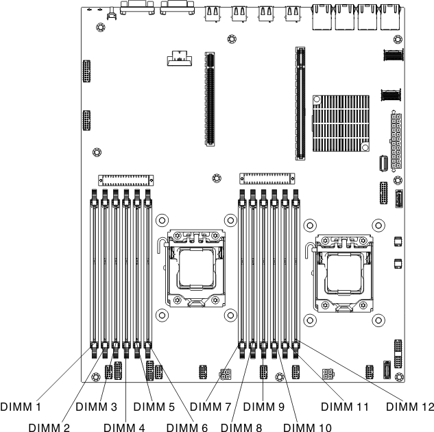
The following illustration shows the location of the DIMM connectors on the system board.
Figure 1. DIMM connectors location


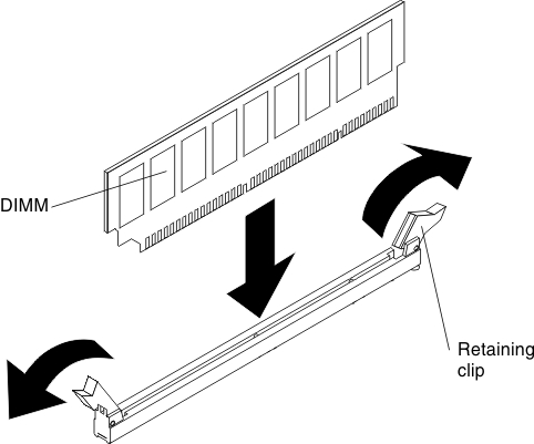
To install a DIMM, complete the following steps:
If you have other devices to install or remove, do so now. Otherwise, go to Completing the installation.
Give documentation feedback
