Replacing a microprocessor and heat sink
Use this information to replace a microprocessor and heat sink
Attention
When you handle static-sensitive devices, take precautions to avoid damage from static electricity. For details about handling these devices, see Handling static-sensitive devices.
Important:
- A startup (boot) microprocessor must always be installed in microprocessor connector 1 on the system board.
- To ensure correct server operation, make sure that you use microprocessors that are compatible and you have installed an additional DIMM for microprocessor 2. Compatible microprocessors must have the same QuickPath Interconnect (QPI) link speed, integrated memory controller frequency, core frequency, power segment, cache size, and type.
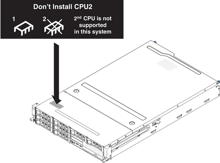
- If you are installing microprocessor Intel E5-1403, E5-1407 or Intel E5-1410, attach the microprocessor information label on the front of the server as the following illustration shows.
- Microprocessors with different stepping levels are supported in this server. If you install microprocessors with different stepping levels, it does not matter which microprocessor is installed in microprocessor connector 1 or connector 2.
- If you are installing a microprocessor that has been removed, make sure that it is paired with its original heat sink or a new replacement heat sink. Do not reuse a heat sink from another microprocessor; the thermal grease distribution might be different and might affect conductivity.
- If you are installing a new heat sink, remove the protective backing from the thermal material that is on the underside of the new heat sink.
- If you are installing a new heat-sink assembly that did not come with thermal grease, see Thermal grease for instructions for applying thermal grease.
- If you are installing a heat sink that has contaminated thermal grease, see Thermal grease for instructions for replacing the thermal grease.
To install an additional microprocessor and heat sink, complete the following steps:
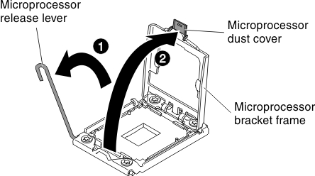
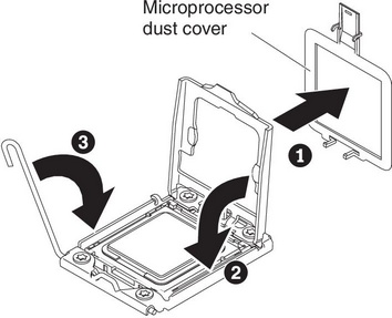
- Open the microprocessor bracket frame by lifting up the tab on the top edge. Keep the bracket frame in the open position.
- Install the microprocessor:
- Align the installation tool with the microprocessor socket as shown in the following illustration.NoteThe microprocessor fits only one way on the socket.
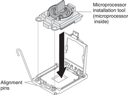
- Twist the handle on the microprocessor tool counterclockwise to insert the microprocessor into the socket.
 Attention
- Do not press the microprocessor into the socket.
- Do not touch exposed pins of the microprocessor socket. The pins on the socket are fragile. Any damage to the pins may require replacing the system board.
- Make sure that the microprocessor is oriented and aligned correctly in the socket before you try to close the microprocessor retainer.
- Do not touch the thermal material on the bottom of the heat sink or on top of the microprocessor. Touching the thermal material will contaminate it and destroys its even distribution. If the thermal material on the microprocessor or heat sink becomes contaminated, you must replace the thermal grease.
- Remove the microprocessor dust cover and store it in a safe place.
- Close the microprocessor bracket frame.
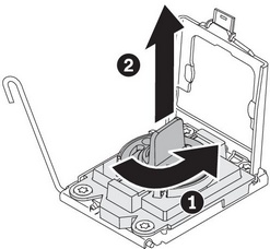
- Close the microprocessor release lever by pressing down on the end, moving it back under the release lever holder underneath the microprocessor bracket.
- Align the installation tool with the microprocessor socket as shown in the following illustration.
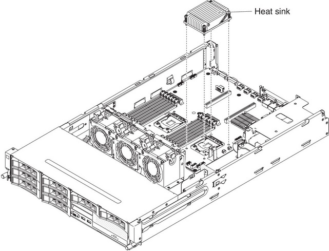
- Install the heat sink that comes with the microprocessor: Attention
- Do not set down the heat sink after you remove the plastic cover.
- Do not touch the thermal material on the bottom of the heat sink. Touching the thermal material will contaminate it. If the thermal material on the microprocessor or heat sink becomes contaminated, contact your service technician.
- Remove the plastic protective cover from the bottom of the heat sink.AttentionDo not touch the thermal grease on the bottom of the heat sink after you remove the plastic cover. Touching the thermal grease will contaminate it. See
Thermal grease for more information. - Align the screws on the heat sink with the screw holes on the system board; then, place the heat sink on the microprocessor with the thermal-grease side down.
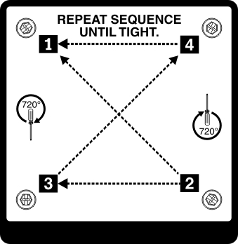
- Press firmly on the captive screws and tighten them with a screwdriver. The follow illustration shows the sequence in tightening the screws, which is also shown on top of the heat sink. Begin with the screw labeled as "1", then "2", "3" and finally "4". If possible, each screw should be rotated two full rotations at a time. Repeat until the screws are tight. Do not overtighten the screws by using excessive force. If you are using a torque wrench, tighten the screws to 8.5 Newton-meters (Nm) to 13 Nm (6.3 foot-pounds to 9.6 foot-pounds).
Give documentation feedback